


58
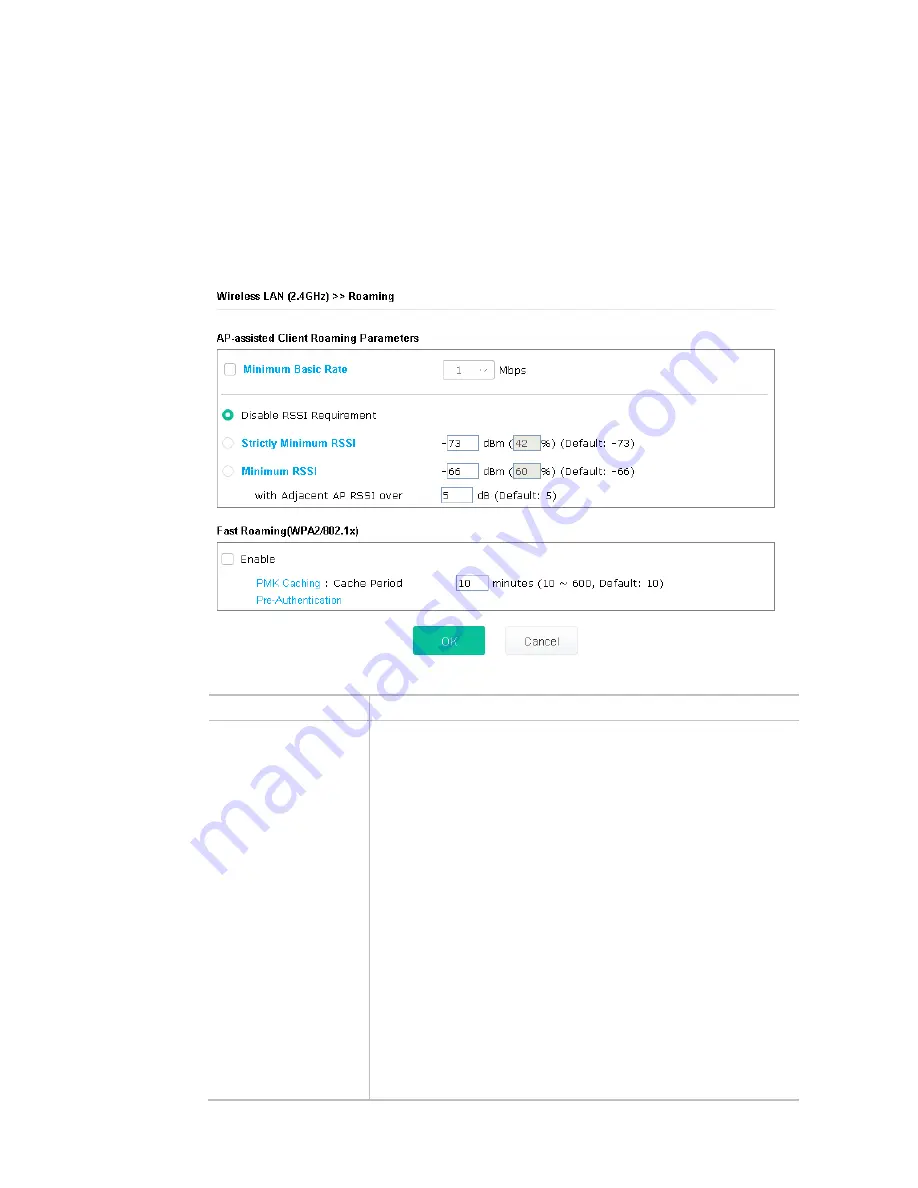
II-3-11 Roaming
The network signal for a single wireless access point might be limited by its coverage range. Therefore, if
you want to expand the wireless network in a large exhibition with a quick method, you can install multiple
access points with enabling the Roaming feature for each AP to reach the purpose of expanding wireless
signals seamlessly.
These access points connecting for each other shall be verified by pre-authentication. This page allows you
to enable the roaming feature and the pre-authentication.
Available settings are explained as follows:
Item
Description
AP-assisted Client
Roaming Parameters
When the link rate of wireless station is too low or the signal received by
the wireless station is too worse, VigorAP 903 will automatically detect
(based on the link rate and RSSI requirement) and cut off the network
connection for that wireless station to assist it to connect another Wireless
AP to get better signal.
Minimum Basic Rate – Check the box to use the drop down list to
specify a basic rate (Mbps). When the link rate of the wireless station is
below such value, VigorAP 903 will terminate the network connection for
that wireless station.
Disable RSSI Requirement - If it is selected, VigorAP will not terminate
the network connection based on RSSI.
Strictly Minimum RSSI - VigorAP uses RSSI (received signal strength
indicator) to decide to terminate the network connection of wireless
station. When the signal strength is below the value (dBm) set here,
VigorAP 903 will terminate the network connection for that wireless
station.
Minimum RSSI - When the signal strength of the wireless station is
below the value (dBm) set here and adjacent AP (must be DrayTek AP and
support such feature too) with higher signal strength value (defined in the
field of With Adjacent AP RSSI over) is detected by VigorAP 903,
VigorAP 903 will terminate the network connection for that wireless
station. Later, the wireless station can connect to the adjacent AP (with
better RSSI).
Summary of Contents for VigorAP 903
Page 1: ...I ...
Page 6: ...Chapter I Installation ...
Page 29: ...23 ...
Page 34: ...28 8 Later a summary page of mesh root with mesh node will be shown on the screen ...
Page 40: ...34 This page is left blank ...
Page 41: ...35 Chapter II Connectivity ...
Page 45: ...39 ...
Page 68: ...62 Below shows how Band Steering works ...
Page 92: ...86 This page is left blank ...
Page 93: ...87 Chapter III Management ...
Page 116: ...110 This page is left blank ...
Page 117: ...111 Chapter IV Others ...
Page 128: ...122 This page is left blank ...
Page 129: ...123 Chapter V Troubleshooting ...
Page 147: ...141 ...


