12
You can find more information in the Chapters A.3, A.4 and A.5.
2.2.9.
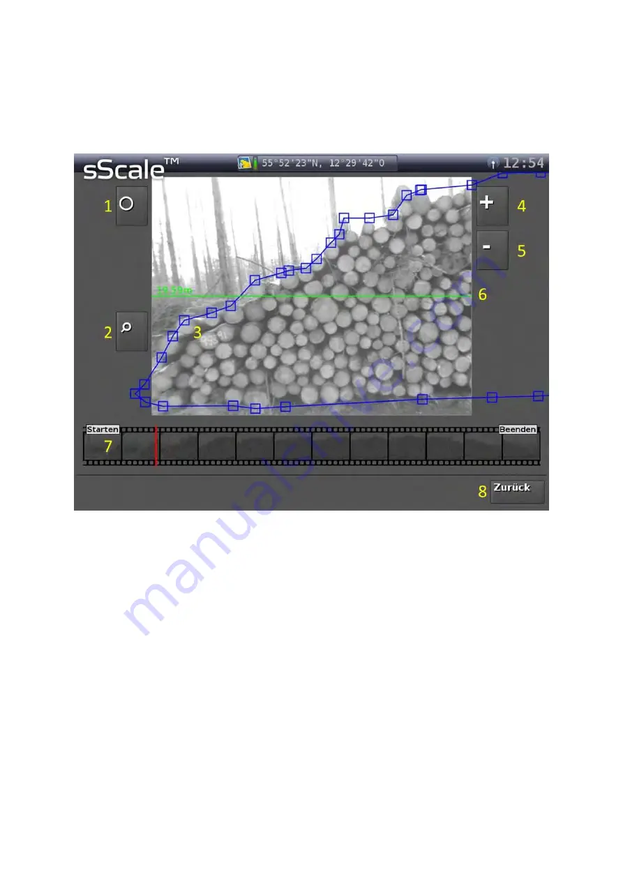
“Edit polygonal course” user interface
1
Button, to enter the diameter-editing mode.
2
Button, to enlarge the representation (zoom).
3
The blue line represents the polygonal course and the blue squares the editable poly-
gon vertices.
4
Button, to enter additional polygon vertices.
5
Button, to remove excess polygon vertices.
6
Green line indicates the total length of the woodpile, defined by the first polygon vertex
on the left side and the last polygon vertex on the right side.
7
Picture sequence of the entire woodpile for quick navigation. The red line shows the
current position within the woodpile.
8
Button, to return to the “Result” user interface.
You can find more information in the Chapters A.3 and A.5.
Summary of Contents for sScale
Page 2: ......
Page 6: ......
Page 9: ...3 Figure 3 Schematic structure of the sScale ...
Page 26: ...20 Figure 9 Automatic generated polygonal course insufficient optimisation ...
Page 27: ...21 Figure 10 Edited polygonal course excessive optimisation ...
Page 28: ...22 Figure 11 Edited polygonal course adequate optimisation ...


