background image


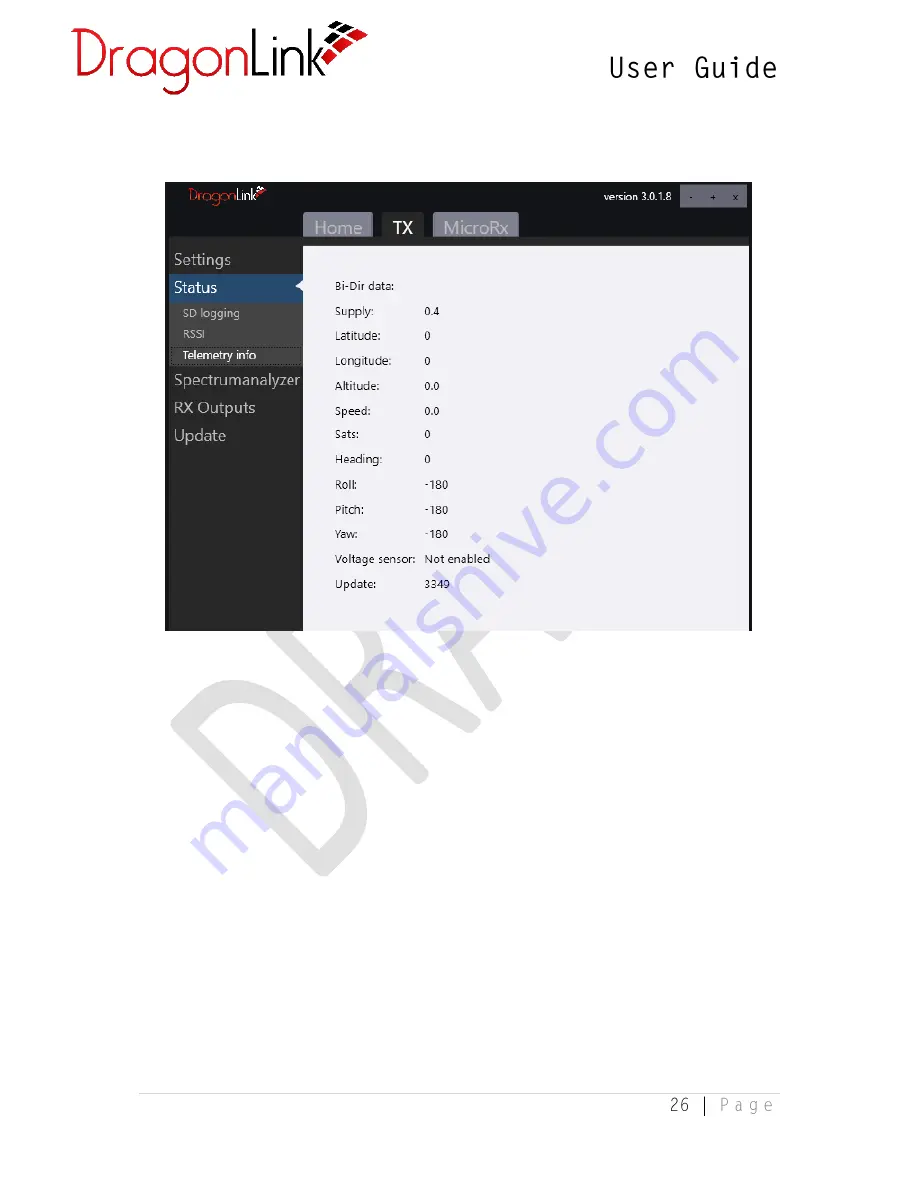
3.2.10 Telemetry Info 


When a compatible GPS, voltage sensor, or OSD are connected to the DragonLink 
receiver and the pin assignments are correctly configured, or when MavLink Decode 
is used to capture telemetry from a valid MavLink stream, the incoming telemetry 
data will be visible on this tab for diagnostic purposes. 


Summary of Contents for V3

Page 1: ...DRAFT ONLY ...

Page 2: ...llation 9 2 4 Applying Firmware Updates 11 3 Configuration DragonLink GUI 13 3 1 DragonLink Transmitter 13 3 1 1 General Settings 13 3 1 2 Channel Mixing Assignment 15 3 1 3 Power Settings 16 3 1 4 RF Settings 17 3 1 5 Alarms and Sounds 18 3 1 6 Presets 20 3 1 7 External Connections 21 3 2 8 SD Logging 24 3 2 9 RSSI 25 3 2 10 Telemetry Info 26 3 2 11 Spectrum Analyzer 27 3 3 DragonLink Transmitter...

Page 3: ...viour 32 3 4 2 Channel Assignment RX Outputs 32 3 5 DragonLink Receiver 33 3 5 1 Receiver Outputs 34 3 5 2 General Settings 36 3 5 3 Radio Modem 37 3 5 4 GPS Settings 38 3 5 5 Log Information 39 3 5 6 RSSI 39 3 5 7 Spectrum Analyzer 40 3 5 8 Stabilization 41 4 Installation 42 4 1 DragonLink Transmitter 42 ...

Page 4: ...are and a telemetry compatible controller Easy to see multi color LEDs for instant status monitoring Audible alarms for low voltage low RSSI etc Logging of flight position etc to Micro SD card in development RF Spectrum Analyzer Super fast update rates available for racers and obstacle flyers Hassle free bind and fly operation for those that want a basic experience Fully compatible with existing D...

Page 5: ...wer Receiver DragonLink 100 amp Current Sensor DragonLink high accuracy GPS position sensor DragonLink Micro OSD 1 3 Specifications DragonLink V3 Advanced Transmitter Slim Input Voltage 5 18v 2 4 cell LiPo Operating Frequency 433MHz frequency hopping in ARS band Typical Range 40km using supplied antennas Weight 90g Length 79mm Width 60mm Thickness 15mm DragonLink V3 Advanced Transmitter Input Volt...

Page 6: ... screen of the DragonLink GUI software This is version 1 0 of the DragonLink User Guide 1 4 2 Known Issues and Limitations When configuring External connections on the Transmitter assigning the same function to more than one connection will cause one or more of those connections to not work When using MavLink Decoded telemetry Mission Planner will endlessly attempt to retrieve parameters As this i...

Page 7: ...ed to pay extra for express mail or very expensive tracking Shipping address ROSA YSLA PO BOX 388 CORTARO AZ 85652 USA Support contact support fpvpro com 1 6 Warnings and Safety The DragonLink system is for hobby use only in radio controlled planes copters boats and cars Use of the system for any other than its intended purpose may cause damage to property personal injury or death Always observe p...

Page 8: ...1024x768 or greater Internet Connectivity 256kbit s or faster recommended 2 2 Obtaining the Latest Software Firmware It is strongly advisable to check for firmware and software updates regularly as they may include bug fixes new features and performance improvements Before flying your DragonLink system for the first time it is necessary to apply the latest firmware and obtain the newest version of...

Page 9: ...ation 1 The compressed zip file obtained from the DragonLink website contains the following files NOTE You will require an internet connection in order to perform the installation as the installer needs to download additional software components 2 Double click the DragonLink_GUI_Setup exe file to begin the installation of the DragonLink software At the prompt select Install ...

Page 10: ...3 Please wait for the download to complete 4 Once the installation is complete the software can be launched from the DragonLink shortcut on the Start Menu ...

Page 11: ...ur device unusable 1 First connect your DragonLink transmitter receiver or OSD to your PC using a micro USB cable Ensure the device tab appears in the DragonLink GUI software It may take a moment for drivers to install before the tab appears If it does not appear please follow the Driver Installation Troubleshooting guide in section to be added 2 Select the relevant tab for the device you wish to ...

Page 12: ...grade to a previous version of firmware After selecting one of the options the software will automatically download the firmware from the internet or allow you to navigate to the firmware file and select it then begin applying it to your DragonLink device NOTE While every precaution is taken to prevent serious bugs making it into any version of our firmware it is possible that beta firmware may co...

Page 13: ...a it will be necessary to re bind your DragonLink transmitter and receiver Saving Settings Before disconnecting or rebooting your DragonLink device ensure that any changes to the configuration are not lost by clicking Save Settings at the bottom of the DragonLink GUI window Some pages have additional save buttons ensure you click these as necessary 3 1 DragonLink Transmitter 3 1 1 General Settings...

Page 14: ...n before powering on the transmitter Switch Ex3 on large transmitter or switch Ex1 on the Slim Once the transmitter is powered on the switch can then be used normally for other functions without affecting the model selection Reboot TX reboots the DragonLink transmitter Required for some changes to take effect Reset TX to factory settings Restores all settings back to factory default A recommended ...

Page 15: ... to the right of each channel show the position of each channel live so you can confirm their functionality without needing the receiver or additional hardware connected CH 1 12 The drop down menus on this screen allow you to assign an input to each of the 12 channels that the DragonLink transmitter communicates to the receiver The available options for each channel include Channels 1 12 from Inpu...

Page 16: ...ould for example be used by the model aircraft to display an indication on the OSD of the transmitter s voltage or for an RTL mode to be set based on low TX voltage or for a physical servo to perform some function once the TX battery reaches a certain level The channel will move from minimum to maximum positions based on a voltage range of approximately 5v 16v 3 1 3 Power Settings The DragonLink t...

Page 17: ...rotary pot is in the upper third of the channel range Power switch Defines the switch RC channel or rotary pot that will be used to alter the transmit power At the time of writing there is no option to remove the assignment of a switch or RC channel to the power setting however if the low mid and high settings are all set to Auto or an identical fixed value the settings on this page will have no e...

Page 18: ...re extreme range and link stability are required NOTE MavLink telemetry streams require a relatively high data rate Without altering the configuration of the flight controller MavLink typically only works with bidir bandwidth set to High and RF preference set to Fastest update rate RF Band to be added Use bi dir Enables or disables bi directional communication between the transmitter and receiver ...

Page 19: ...hree beeps will be played to correspond with the selection of either low mid or high power levels respectively When using Auto power level modes only disabling this alert is recommended see section 4 1 3 Micro Power mode Plays a repeating audio reminder while the transmitter is in micro power range test mode Servo test mode Plays a repeating audio reminder while the transmitter is in servo test mo...

Page 20: ...eneral settings such as channel and switch assignments model ID or alarms however it will alter settings to do with bi directional data update rate and bandwidth in order to optimise performance for the use case determined by the preset After applying a preset it will be necessary to check all of the settings to confirm they are suitable ...

Page 21: ...d ground station setups Bluetooth on supported models Sets the type of data that will be streamed to the Bluetooth virtual COM port Option Function Bi directional Radio modem Passes raw serial data directly to and from the connected device Yes DragonLink Mavlink Encodes non MavLink telemetry from the aircraft into a MavLink compatible telemetry stream for use with ground stations No Auto detect RX...

Page 22: ... the module to crash and require reset of the DragonLink transmitter NOTE This issue does not affect newer Slim transmitters with an updated bluetooth module and thus this setting has no effect Expansion con Sets the type of data that will be streamed to the UEXP port on the base of the transmitter Option Function Bi directional Radio modem Passes raw serial data directly to and from the connected...

Page 23: ... non MavLink telemetry from the aircraft into a MavLink compatible telemetry stream for use with ground stations No GUI config Allows the connected device to configure the transmitter using the DragonLink GUI N A NOTE Baud rates do not apply to the USB virtual COM port As long as the baud rate is correct on the receiver and the receiving software matches that setting the data will parse successful...

Page 24: ...3 2 8 SD Logging This page allows you to see diagnostic information regarding the logs that have been saved to the SD card not included At the time of writing support for logging is still in development ...

Page 25: ...s displayed in live graph view along with the transmitter input voltage This indication of RSSI represents the strength of the telemetry signal sent from the receiver to the transmitter and not the strength of the RC signal sent from the transmitter to your model aircraft ...

Page 26: ...r or OSD are connected to the DragonLink receiver and the pin assignments are correctly configured or when MavLink Decode is used to capture telemetry from a valid MavLink stream the incoming telemetry data will be visible on this tab for diagnostic purposes ...

Page 27: ...e cause of any radio interference from other components on your model aircraft The example screenshot above shows an RF noise floor the signal strength of average background noise of approximately 120dBm across the 433mHz band 427 437mHz which is ideal It is normal to see a spike on the spectrum analyzer when your DragonLink receiver is powered on and within range ...

Page 28: ...onditions matching those of the planned flight To conduct a range test 1 Hold down the Menu button on the DragonLink transmitter and turn on the power 2 After the power on sound is played the LED s will turn green accompanied by 1 beep 3 Release the Menu button 4 The transmitter will continue to play 1 beep if the range test mode alarm is enabled and the LED s will flash green to indicate it is in...

Page 29: ...larm is enabled and the LED s will flash blue to indicate it is in binding mode 4 Power on the receiver 5 The receiver s blue and green LEDs should both begin flashing to indicate a successful bind 6 Power off both the receiver and the transmitter to save the binding 3 3 3 Servo Test In servo test mode the DragonLink transmitter will continuously sweep all channels back and forth from minimum to m...

Page 30: ...ng the USB function setting on the DragonLink transmitter it will no longer be possible to configure the transmitter using the USB port and GUI software To restore the default USB mode 1 Hold down the Menu button on the DragonLink transmitter and turn on the power 2 After the power on sound is played continue to hold the menu button until the LED s on the transmitter turn white accompanied by 5 be...

Page 31: ...of all sticks switches and rotary pots should now be saved to the receiver WARNING Prior to setting the failsafe channel positions ensure the position of any mode switches such as arm or return to home are in the position you wish them to remain should the R C link be lost 3 4 DragonLink Receiver via Transmitter ...

Page 32: ...gh this page For those items the PC will need to be directly connected to the receiver If the fields on this page are blank settings can be retrieved from the receiver using the Update info button If this does not work ensure the receiver is powered on and has been bound to the transmitter NOTE Ensure settings are saved on this page using the dedicated Save settings button 3 4 1 RX Failsafe Behavi...

Page 33: ...n CH8 of the Micro receiver On the Advanced high power receiver there is a dedicated set of pins CH 13 for this function 3 5 DragonLink Receiver The first time you connect your DragonLink receiver to the DragonLink GUI you may be prompted to set the receiver type Ensure that you select this correctly as an incorrect selection may result in unusable channels ...

Page 34: ...updated until the signal from the transmitter is re acquired Keep position All channels will hold their last known position until signal is re acquired WARNING Where applicable if using Keep position you may need to ensure that your flight controller is correctly configured to monitor the DragonLink receiver s RSSI value in order for it to correctly identify when a fail safe event has occurred Rec...

Page 35: ...NOTE Analog RSSI is only selectable on channel 8 micro RX or channel 13 advanced RX ...

Page 36: ...rectional An additional 4 channels are visible in the GUI when connected to an Advanced receiver PPM S bus out These drop down menus allow you to assign channels to the PPM or S BUS stream and select the number of channels to include The maximum number of channels for either protocol is 12 UEXP con pin3 4 These connectors can also be assigned various functions including S BUS PPM GPS input Serial ...

Page 37: ...d as such it should never need to be changed This configuration is needed internally for the firmware to handle pin assignments and configuration This is normally set once when first connected to a PC however it can be changed here if it is inadvertently set incorrectly Set hardware ID Confirms the change to the above setting Reset hardware to Factory Settings Restores all of the configuration to ...

Page 38: ...icantly greater range and robustness of data Please see chapters to be added which contain detailed instructions for correctly applying this setting 3 5 4 GPS Settings A GPS receiver can be directly connected to the DragonLink Receiver for telemetry purposes You will need to know the baud rate for the GPS receiver attached receiver which is set using the drop down menu and saved by clicking Save G...

Page 39: ...Information page is used to store certain flight data regarding channel positions RF transmit power GPS and telemetry data and link state This can be enabled disabled deleted and retrieved using the controls on this page 3 5 6 RSSI ...

Page 40: ... used for troubleshooting or testing In addition the voltage supplied to the Receiver is super imposed on the graph in orange 3 5 7 Spectrum Analyzer This feature is identical to the feature of the same name found in the Transmitter configuration pages Please see chapter 3 2 11 for further information ...

Page 41: ...3 5 8 Stabilization to be added ...

Page 42: ...y hook and loop pads with self adhesive backing which can be used to fix your transmitter to the back of your controller as per the below image If this method is not suited to your controller other mounting hardware may be required not included Connection to Trainer Port The trainer port is the output on your controller which sends the positions of the channels to the DragonLink Transmitter On mos...

Page 43: ...le option was selected at the time of purchase you should have received the cable with one end having a plug matching the picture below This can be connected directly onto the RF module pins as shown Ensure the cable is not connected to the module bay pins in reverse 3 5mm Jack Connector This is the most common type of connection for Spektrum JR Walkera Hitech and other brands of RC controllers Tw...

Page 44: ...ovided using the 3 5mm jack 18 volts This is provided using the red connector Futaba Square Trainer Port The Futaba square trainer cable will supply both signal and power to the DragonLink Transmitter and cannot be connected with incorrect polarity ...

Page 45: ...he DragonLink Transmitter if not already done so This should be connected to Input 1 Note that on the Large DragonLink Transmitter that Input 2 does not supply power to the unit Configuration The controller must be configured to output a signal matching one of the selectable options found in chapter 3 1 1 ...

Reviews: