background image

PAGE 13

FAILURE

PROBABLE CAUSE

TROUBLE SHOOTING 

CONTINUED

Brake will not hold load.

Brake vibrates or chatters when lowering load.

a)

Hydraulic system back pressure not per SPECIFICATIONS.
Refer to procedure described in TROUBLE SHOOTING -
HYDRAULIC SYSTEM PRESSURE AND PLANEMATIC
TORQUE to verify system back pressure at motor.

b)

Brake piston release oil being trapped by hydraulic system
control valve. Control valve spool must open motor ports to
reservoir when in the neutral position. Refer to
RECOMMENDATIONS - HYDRAULIC CONTROL VALVE.

c)

Worn brake and/or divider plates. Inspect brake plates and
divider plates for wear as described in SERVICE
INSTRUCTIONS - DISASSEMBLY OF BRAKE ASSEMBLY.

d)

Damaged brake and/or divider plates. Plate discolouration
and distortion will occur if plates overheat due to insufficient
circulation flow. Required brake circulation flow is listed in
SPECIFICATIONS. Plate abrasion damage will occur if
contamination is present in hydraulic fluid.

e)

Damaged over-running clutch. Inspect sprag clutch,
connecting shaft and motor drive shaft as described in
SERVICE INSTRUCTIONS - DISASSEMBLY OF BRAKE
ASSEMBLY.

f)

Damaged brake springs. Measure brake springs as
described in SERVICE INSTRUCTIONS - DISASSEMBLY
OF BRAKE ASSEMBLY. Verify springs are straight and
length is as indicated.

g)

Seized brake piston. Brake piston could be seized by
hydraulic fluid contamination, scored brake housing bore or
damaged piston O-rings.

a)

Inadequate hydraulic flow. Refer to procedure described in
TROUBLE SHOOTING - HYDRAULIC SYSTEM VOLUME
AND PLANEMATIC SPEED to verify supply.

b)

Inadequate hydraulic control. System control valve must
have good metering characteristics.

c)

Foamy hydraulic fluid. Foam will occur if air is mixed with
hydraulic oil.

d)

Worn brake and/or divider plates. Inspect brake plates and
divider plates for wear as described in SERVICE
INSTRUCTIONS - DISASSEMBLY OF BRAKE ASSEMBLY.

e)

Damaged brake plates and/or divider plates. Plate
discolouration and distortion will occur if plates overheat
due to insufficient circulation flow. Required brake circulation
flow is listed in SPECIFICATIONS. Plate abrasion damage
will occur if contamination is present in hydraulic fluid.

f)

Damaged over-running clutch. Inspect sprag clutch, connecting
shaft and motor drive shaft as described in SERVICE
INSTRUCTIONS - DISASSEMBLY OF BRAKE ASSEMBLY.

a)

Damaged O-ring. Static O-rings seal between the end
cover and final housing, final housing and brake housing ,
brake housing and motor adaptor. Another O-ring seals
brake release pressure between the motor adaptor and
brake housing. A failed O-ring will result in oil leakage at
that particular area.

b)

Worn or damaged output shaft seal. Excessive circulation
return line back pressure can damage this seal. Refer to
procedure described in TROUBLE SHOOTING - HYDRAULIC
SYSTEM PRESSURE AND PLANEMATIC TORQUE to
measure back pressure. Back pressure must never exceed
the allowable circulation return line back pressure listed in
SPECIFICATIONS. Back pressure will be higher at start-up
and during cold weather when oil viscosity is greater.

Oil leaks.

338 REV.990801

Refer to the SERVICE INSTRUCTIONS if it becomes necessary to disassemble the Planematic drive.

Summary of Contents for TWG PULLMASTER PH50

Page 1: ...LE TO ALL PERSONS RESPONSIBLE FOR THE OPERATION INSTALLATION SERVICING AND MAINTENANCE OF THIS PRODUCT INSTRUCTION AND PARTS MANUAL MODEL PH50 PLANEMATIC DRIVE THE LOGICAL CHOICE TWG Headquarters 11135 S James Ave Jenks OK 74037 USA 918 298 8300 salesinfo dovertwg com TWG Canada 19350 22nd Ave Surrey BC V3Z 3S6 CANADA 604 547 2100 salesinfo dovertwg com ...

Page 2: ...s that this Warranty does not cover failures of the unit which result in any manner from the operation of the machine or unit at vibration frequencies at or near the natural frequency vibration of the machine in such a way that damage may result Buyer expressly agrees that Seller is not responsible for failure damage or accelerated wear caused by machine or ambient vibration Further Buyer acknowle...

Page 3: ... 11 Warm up equipment before operating Planematic drive particularly at low ambient temperatures 12 Do not weld any part of the Planematic drive 13 Verify circulation return before operating Planematic drive 14 Ensure equipment stability before operating Planematic drive 15 Wear proper clothing to avoid entanglement in rotating machinery 16 Always stand clear of the load 17 Use only recommended hy...

Page 4: ...from the reversing side of the hydraulic motor is channelled to the brake piston causing the brake piston to release the multi disc brake against the brake springs The sprag clutch locks motor drive shaft with the connecting shaft Connecting shaft coupled with brake hub and primary internal gear causes the primary reduction to rotate at the rpm of hydraulic motor thus eliminating the primary reduc...

Page 5: ... 9 Automatic brake counterclockwise shaft rotation external brake release external circulation flow 10 Automatic brake counterclockwise shaft rotation external circulation flow 11 Brake effective in both directions external circulation flow 17 Brake effective in both directions external circulation flow external brake release Automatic brake spring applied automatically released by the hydraulic p...

Page 6: ...d or splined output shafts or adaptor flanges are optionally available OPTIONAL GEAR SECTION FOR THE HYDRAULIC MOTOR The performance of the standard PULLMASTER Planematic drive can be changed by using different gear sections Contact the factory for performance information HYDRAULIC MOTORS FOR HIGH PRESSURE HYDRAULIC SYSTEMS The operating pressure of the standard PULLMASTER Planematic drive is limi...

Page 7: ...PUT RPM Forward 48 rpm Reverse 208 rpm MAXIMUM OPERATING PRESSURE 2200 psi 152 bar MAXIMUM OPERATING VOLUME 50 US gpm 189 l min MINIMUM OPERATING VOLUME 17 US gpm 64 l min REDUCTION RATIO Forward 41 2 1 Reverse 9 5 1 OUTPUT SHAFT Axial or Radial load See OVERHUNG LOAD RATING PERFORMANCE AT VARYING PRESSURE OR VOLUME See PERFORMANCE GRAPHS PERMISSIBLE SYSTEM BACK PRESSURE AT MOTOR RETURN PORT 65 ps...

Page 8: ...le B a bearing geometry constant 3 10 T basic thrust or tension load 25 300 c basic load constant 51 000 L allowable overhung load in lbs y distance of load centre to mounting face in inches up to full load occasionally Intermittent duty at variable loads 3 hr day intermittent duty full load 8 hr day continuous duty full load 24 hr day continuous duty full load 0 75 1 00 1 50 2 68 1 00 1 25 1 50 2...

Page 9: ...or and gear ratio F O R W A R D REVERSE FORWARD R E V E R S E 210 180 150 120 90 60 30 4519 40 000 3390 30 000 2260 20 000 1130 10 000 138 2000 110 1600 83 1200 55 800 28 400 OUTPUT TORQUE Nm 2200 0 50 40 30 20 10 0 50 000 0 0 5649 152 0 OUTPUT TORQUE lb in OIL PRESSURE psi OIL PRESSURE bar 0 0 OUTPUT RPM 38 76 114 151 189 OIL VOLUME US gpm OIL VOLUME l min ...

Page 10: ...ED FOR MODELS 2 US GPM 8 L MIN 800 PSI 55 BAR FILTER PUMP HYDRAULIC RESERVOIR RETURN TO CENTER 4 WAY SPRING MOTOR SPOOL CONTROL VALVE RELIEF VALVE PRESSURE TO RESERVOIR MUST GO DIRECT CIRCULATION RETURN LINE MODELS ONLY EXTERNAL CIRCULATION PH50 4 5 US GPM 17 LPM PM50 3 5 US GPM 13 LPM CIRCULATION SUPPLY LINE ...

Page 11: ...0 microns Dusty Atmosphere 5 microns In order to prevent accidental stoppage of the return line flow the oil filter should have a by pass feature HYDRAULIC FLUID ThehydraulicfluidselectedforusewithPULLMASTER Planematic drives should be a high grade petroleum based fluid with rust oxidation and wear resistance Fluid cleanliness and operating viscosity are critical to drive reliability efficiency an...

Page 12: ...olts grade 5 or better Evenly tighten bolts per BOLT TORQUE CHART 5 Use only recommended circuit components and hydraulic hoses 6 Plumb a separate circulation return line directly to tank Keep the return line above the drive to maintain housing oil level at all times 7 Fill Planematic drive housing with oil through filler drain port before operating Units ported for external circulation can be fil...

Page 13: ...otor is supplied through a single lever control valve with reverse neutral and forward positions Drive speed is regulated by metering the control valve lever Standard brake automatically releases when driving in reverse direction and sets when control valve lever is returned to neutral position Refer to OPTIONS section of this manual for explanation of optional brake configurations 3 Verify instal...

Page 14: ... and or pressure loss include the hydraulic pump relief control valves and slipping belts on a v belt driven pump If the hydraulic volume and pressure are per specification refer to the following TROUBLESHOOTING chart to identify failure probable causes TROUBLE SHOOTING Drive will not produce maximum rated torque as listed in SPECIFICATIONS a Hydraulic system supply pressure or back pressure not p...

Page 15: ...TROUBLESHOOTING HYDRAULICSYSTEMVOLUME AND PLANEMATIC SPEED to verify supply b Inadequate hydraulic control System control valve must have good metering characteristics c Foamy hydraulic fluid Foam will occur if air is mixed with hydraulic oil d Worn brake and or divider plates Inspect brake plates and divider plates for wear as described in SERVICE INSTRUCTIONS DISASSEMBLYOFBRAKEASSEMBLY e Damaged...

Page 16: ...ERPlanematicdrive Therearenospecialtoolsneededforserviceorrepairworkandnoadjustments or calibrations are necessary Proceed with the disassembly as follows DISASSEMBLY OF HYDRAULIC MOTOR ASSEMBLY If the analysed service or repair work requires access to the interior of the brake housing the hydraulic motor should not be disassembled In this case the hydraulic motor should be removed together with t...

Page 17: ...ing circlip item 727 from motor drive shaft item 730 Remove sprag clutch aligner item 724 support washer item 717 and sprag clutches item 723 from motor drive shaft Inspect bore of connecting shaft and outer diameter of motor drive shaft where both parts engage with sprag clutches If parts show any deep indentations or surface damage they must be replaced 3 Remove connecting shaft item 600 togethe...

Page 18: ...EMBLY OF FINAL DRIVE AND OUTPUT SHAFT ASSEMBLY Refer to PARTS REFERENCE on page 22 and FINAL DRIVE GROUP drawing G1037A on page 23 If final drive or output shaft assembly requires service or repair disassemble as follows 1 Remove final sungear item 340 from center of three final planet gears item 320 2 Pull out final planet hub assembly and inspect for wear or damage If final planet hub gears item...

Page 19: ...EMBLY Reassemble brake housing assembly by reversing disassembly procedure 1 Install new well greased O rings item 751 and 753 into glands of brake piston item 750 2 Slide brake piston into brake housing with holes for brake springs facing out of brake housing see BRAKE GROUP drawing 3 Install 16 brake springs item 752 in brake piston Piston has 18 holes and two holes which have no brake springs i...

Page 20: ...c motor 2 Install six new pocket seals item 887 on each thrust plate item 885 Seal kit includes a single strip of rubber Using a sharp knife cut lengths to fit openings in thrust plates Press one thrust plate together with six pocket seals onto bearings item 875 installed in motor adaptor item 800 so pocket seals are against motor adaptor 3 Install new well greased body seal item 869 on each side ...

Page 21: ...perating Planematic drive ensure that circulation oil is being supplied to brake housing If an internal circulation model fill with hydraulic oil through the uppermost drain port before running To ensure proper reassembly run Planematic drive in both directions without load To ensure proper reinstallation refer to test procedures described in INSTALLATION and OPERATING INSTRUCTIONS ...

Page 22: ...Discard and replace all O rings and oil seals 4 Inspect all parts for wear and replace if necessary 5 Clean all parts thoroughly with solvent before reassembly 6 Follow INSTALLATION and OPERATING INSTRUCTIONS when returning Planematic drive to its mounting When ordering parts for the PULLMASTER Planematic drive always quote the complete model and serial numbers of the unit MODEL NO _______________...

Page 23: ...PAGE 21 ASSEMBLY DRAWING 338 REV 031001 G1033 A G1037 A G1038 ...

Page 24: ...808 CAPSCREW HEX HEAD 1 4 20 NC X 1 00 GRADE 5 165 6 25130 LOCKWASHER 1 4 167 1 25061 O RING 163 6 ID 3 32 CS 300 1 21414 PLANET HUB 310 3 20162 PLANET PIN 311 3 25122 CIRCLIP ROTOR CLIP C 100 313 3 25411 CIRCLIP ROTOR CLIP SH 100 320 3 20158 PLANET GEAR 321 6 25098 THRUST WASHER TORRINGTON TRA 1625 323 3 25097 NEEDLE BEARING TORRINGTON BH1620 340 1 21418 SUNGEAR 341 1 25809 CIRCLIP ANDERTON A1000...

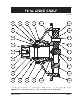
Page 25: ...sent in a specific assembly Parts that are referenced on the drawing but are not on the PARTS REFERENCE list should be ignored G1037 A 338 REV 990801 FINAL DRIVE GROUP 156 157 320 161 149 159 160 103 165 152 154 155 153 150 163 167 151 311 323 313 321 310 340 341 300 100 ...

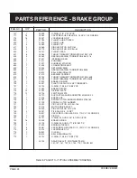
Page 26: ...T THREADED 707 1 25192 O RING 174 8 3 4 ID 3 32 CS 712 1 21484 BRAKE SPACER 714 13 21252 DIVIDER PLATE 715 12 25194 FRICTION PLATE 717 1 25729 SUPPORT WASHER ANDERTON R 28 40 2 0 720 1 21426 BRAKE HUB 723 2 25187 SPRAG CLUTCH BORG WARNER X138769 724 1 21193 SPRAG CLUTCH ALIGNER 727 1 25492 CIRCLIP ROTOR CLIP SH 106 730 1 21416 MOTOR DRIVE SHAFT 731 1 25500 CIRCLIP ROTOR CLIP C 93 743 2 25237 PIPE ...

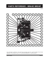
Page 27: ... referenced on the drawing but are not on the PARTS REFERENCE list should be ignored G1038 338 REV 990801 PARTS REFERENCE BRAKE GROUP 410 113 111 107 779 751 615 703 752 770 430 400 777 444 440 775 411 421 423 420 771 773 745 413 743 700 714 707 715 610 750 617 720 602 603 609 723 717 731 730 600 724 727 753 304 ...

Page 28: ...T 097 2 GEAR WIDTH 885 2 25725 THRUST PLATE 887 12 25656 SEAL POCKET 899 2 25031 PIPE PLUG 1 4 18 NPT 929 1 950 1 SUB ASSY MOTOR 097 2 GEAR WIDTH 951 4 25324 CAPSCREW HEX HEAD 5 8 11NC X 5 25 GRADE 5 953 4 25325 WASHER 955 2 25557 PLASTIC CAPLUG 1 625 12 THREADED 23121 MOTOR SEAL KIT CONTAINS ITEMS 869 877 AND 887 These parts vary according to Brake Code Refer to APPENDIX B ITEM 950 MOTOR SUB ASSY...

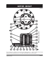
Page 29: ...embly Parts that are referenced on the drawing but are not on the PARTS REFERENCE list should be ignored G1033 A 338 REV 031001 MOTOR GROUP ITEM 823 MAY BE 113 IN BOM ITEM 929 MAY BE 503 IN BOM 899 870 875 865 861 887 821 823 881 800 877 953 951 955 803 804 885 869 802 801 805 807 809 950 929 ...

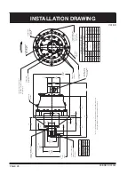
Page 30: ...TERNAL BRAKE RELEASE PORT 1 8 27 NPT GAUGE PORTS 1 4 18 NPT 2 PULLER HOLES 1 4 18 NPT 393 70 BC DIA 15 503 15 497 25 32 19 8 ON 8 MOUNTING HOLES DRAIN PORT 3 4 14 NPT 625 15 9 FLANGE 6 HOLES OPTIONAL OUTBOARD 6 HOLES 625 15 9 OPTIONAL INBOARD FLANGE 428 6 16 88 MOTOR PORTS SAE O RING BOSS SEE MOTOR CHART FOR SIZES 5 8 11NC LIFTING HOLE 163 6 4 1 25 SPLIT FLANGE 2 00 139 156 6 2 1 312 12 1 75 114 9...

Page 31: ... 21399 21399 21804 22165 150A KEY N A 22203 N A N A N A N A 152 FLANGE N A N A 21419 21805 N A N A 153 CAPSCREW N A N A 25139 25139 N A 25013 154 FLANGE CAP N A N A 21420 21420 N A 22166 155 LOCKWASHER N A N A 25359 25359 N A 25014 1 2 3 4 5 6 PART NUMBER 5 8 11NC X 1 5 1 2 13NC X 1 25 5 8 1 2 QTY 2 QTY 2 ...

Page 32: ... 25040 N A 25622 25622 N A N A 25622 25622 N A N A 25374 25374 N A N A 25374 25374 N A N A N A N A N A 25393 25393 25393 25393 25085 25085 25085 25085 N A N A N A N A 21938 22014 22015 22016 22017 22018 22019 22020 SHUTTLE ORIFICE PLUG 1 8 27 NPT PIPE PLUG 1 8 27 NPT PIPE PLUG 1 8 27 NPT PIPE ADAPTOR 1 8 NPT CAPLUG 3 8 NPT CAPLUG 3 8 18 NPT PIPE PLUG MOTOR SUB ASSY BRAKE CODE ITEM NO PART DESCRIPT...

Page 33: ...6 50 68 1 2 75 102 9 16 110 149 5 8 150 203 3 4 265 359 7 8 420 569 1 640 868 1 1 8 800 1085 1 1 4 1000 1356 1 3 8 1200 1627 1 1 2 1500 2034 NOTE Unless otherwise specified torque bolts per above chart TORQUE Nm TORQUE Lb ft BOLT DIAMETER Inches 338 REV 990801 ...

Reviews: