PAGE 15
SERVICE INSTRUCTIONS
CONTINUED
338 REV.031001
NOTE:
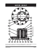
Pocket seals, body seals, and ring seals in the hydraulic motor assembly are not part of the PULLMASTER
Planematic drive seal kit. The seal kit for the hydraulic motor can be ordered from the factory under Part
No. 23121.
REMOVAL OF HYDRAULIC MOTOR ASSEMBLY:
If disassembly of the hydraulic motor is not necessary, proceed as follows:
1) Remove 12 hex capscrews item 821, together with lockwashers item 823, from motor adaptor item 800. Since
brake springs item 752, apply pressure against inside of motor adaptor, it is recommended that hex
capscrews are unscrewed, one turn at a time, until spring pressure has been released. Complete motor
assembly, including motor adaptor, can now be removed from brake housing
2) For models with internal circulation, ensure that hole in orifice plug item 804, is clear. For models with external
brake release option, verify that shuttle item 802, moves freely.
3) Remove and discard O-ring item 801, and O-ring item 707. (O-ring item 801, seals pressure transfer hole
for automatic brake release and is situated on flange of brake housing.)
4) Remove bearing carrier item 610, with ball bearing item 609. Inspect ball bearing item 609, and replace if
necessary.
5) Proceed to applicable DISASSEMBLY OF BRAKE ASSEMBLY.
DISASSEMBLY OF BRAKE HOUSING ASSEMBLY:
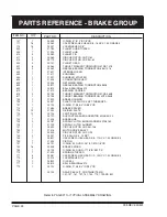
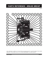
Refer to BRAKE GROUP drawing G1038 on page 25.
1) Pull motor drive shaft item 730, along with sprag clutches item 723, out of connecting shaft item 600.
2) Disassemble sprag clutch assembly by removing circlip item 727, from motor drive shaft item 730. Remove
sprag clutch aligner item 724, support washer item 717, and sprag clutches item 723, from motor drive shaft.
Inspect bore of connecting shaft and outer diameter of motor drive shaft where both parts engage with sprag
clutches. If parts show any deep indentations or surface damage, they must be replaced.
3) Remove connecting shaft item 600, together with brake hub item 720.
4) Remove retaining ring item 602, to disassemble brake hub from connecting shaft and inspect needle bearing
item 603. If needle bearing is damaged, press out of connecting shaft and replace.
5) Remove 13 divider plates item 714, and 12 friction plates item 715, and inspect for damage or wear. Plates
should be flat and smooth. Plates should not show heat discolouration. Fibre material on friction plates should
be intact and grooved. Replace plates if damaged.
6) Remove internal gear item 430, two thrust washers item 615, and thrust bearing item 617.
7) Remove primary sungear item 440, from center of primary planet hub item 400.
8) Pull primary planet hub assembly out of ball bearing item 777, and oil seal item 775.
9) Remove 16 capscrews item 111, and lockwashers item 113, to separate brake housing item 700, from final
housing item 100.
10) Remove and discard O-ring item 107.
11) Remove six capscrews item 771, and lockwashers item 773, one turn at a time, to relieve pressure being
exerted by brake springs item 752.
12) Remove spring stopper item 770, and discard O-ring item 779.
13) Check planet hub stopper item 304, on spring stopper item 770, for wear and replace if less than 0.21 inch thick.
14) Press ball bearing item 777, out of spring stopper item 770. Remove and discard oil seal item 775.


