


PAGE 16
SERVICE INSTRUCTIONS
CONTINUED
338 REV.031001
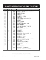
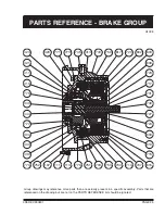
15) Remove 16 brake springs item 752. Examine springs for damage and measure overall length. Overall spring
length should be 1.99 inch. Springs measuring less than 1.93 inch should be replaced.
16) Pull brake piston item 750, out of brake housing, using two tapped holes in brake piston and two 1/2 inch -
13 NC capscrews. (Two capscrews item 771, from spring stopper item 770, can be used. Alternatively, turn
brake housing over and gently tap uppermost surface of brake piston with soft-headed hammer until it falls
out onto workbench.)
17) Remove and discard O-ring item 751, and O-ring item 753.
18) Check brake piston outside diameters and inside diameters of brake housing for surface scratches due to
particles in hydraulic fluid (contamination). If there is any evidence of surface damage, polish with fine emery cloth.
DISASSEMBLY OF PRIMARY PLANET HUB ASSEMBLY:
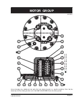
Inspect three primary planet gears item 420, for damage or wear. If necessary, disassemble as follows:
1)
Remove circlips item 411, and press planet pins item 410, out of primary planet hub item 400. Remove planet
gears item 420, and inspect needle bearings item 423, and two thrust washers item 421. Replace if damaged.
2) Press sungear stopper item 444, out of primary planet hub and measure thickness. If less than 0.21 inch
thick, replace sungear stopper.
All parts have now been removed from brake housing and there is no need for further disassembly unless a failure
has been analysed in the remaining drive assembly.
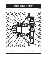
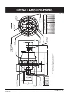
DISASSEMBLY OF FINAL DRIVE AND OUTPUT SHAFT ASSEMBLY:
Refer to PARTS REFERENCE on page 22 and FINAL DRIVE GROUP drawing G1037A on page 23.
If final drive or output shaft assembly requires service or repair, disassemble as follows:
1) Remove final sungear item 340, from center of three final planet gears item 320.
2) Pull out final planet hub assembly and inspect for wear or damage. If final planet hub gears item 320, require
removal, take off circlip item 311, from planet pin item 310, and press planet pin out of final planet hub item
300. Remove final planet gear item 320, and inspect thrust washers item 321, and needle bearing item 323.
Replace if damaged.
3) If Planematic drive includes an inboard or outboard flange, remove capscrew item 153, lockwasher item 155,
and flange cap item 154, to slide off flange item 152.
4) Remove six hex capscrews item 163, and lockwashers, item 165. Pull off end cover item 156, and discard
O-ring item 167, and oil seal item 157.
5) Untab lockwasher item 161, from locknut item 159. Unscrew locknut and remove lockwasher and keyed washer
item 149. Output shaft item 150, can now be pressed out of tapered roller bearings items 151 and 103.
6) Check sungear stopper item 160, for wear and replace if less than 0.21 inch thick.
The Pullmaster Planematic drive has now been completely disassembled.
REASSEMBLY
Thoroughly clean all parts. Use only new, well-greased O-rings and oil seals. Unless otherwise specified, torque
fasteners per BOLT TORQUE CHART.
REASSEMBLY OF FINAL DRIVE AND OUTPUT SHAFT ASSEMBLY:
Reassemble final drive and output shaft assembly by reversing disassembly procedure.
1) Press sungear stopper item 160, into end of output shaft item 150, and press output shaft into tapered roller
bearings items 151 and 103.