


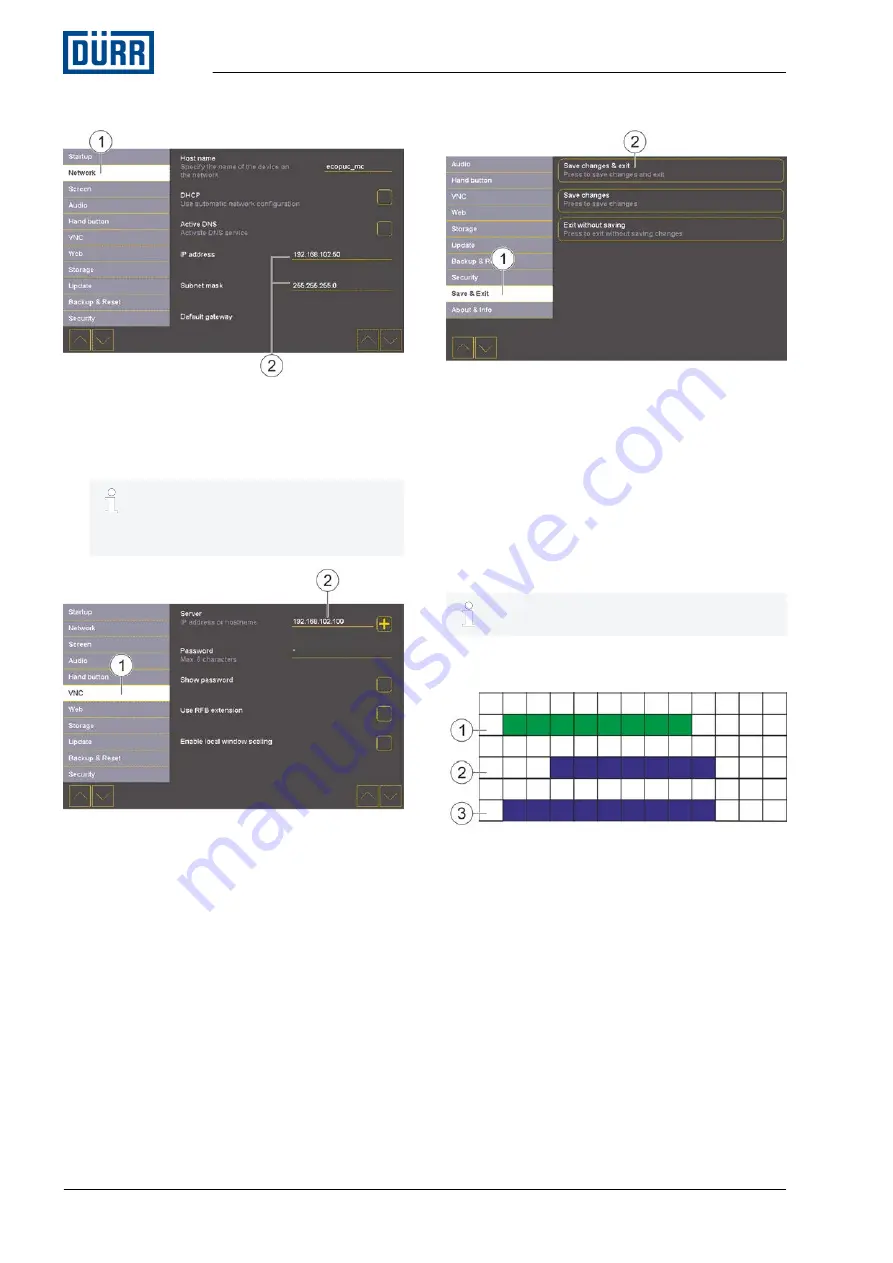
Fig. 48: Touch display menu
12. Tap
“Network”
(1) in the Menu bar.
13. Adjust IP address and subnet mask (2) of the
Touch display.
IP address of the Touch display and
of the PLC interface may not be iden-
tical. The IP address must however
be in the same subnet.
Fig. 49: VNC-settings (Touch-Display)
14. Tap
“VNC”
(1) in the Menu bar.
15. Enter the same IP Address (2) as entered in
step 9.
Fig. 50: Save & Exit
16. Tap
“Save & Exit”
(1) in the Menu bar.
17. Tap button (2).
ð
Settings are saved. Touch-Display is con-
nected to PLC.
Menu of the Touch Display closes.
8.5.9 Flow chart of the external interface
The following charts are examples for flow charts
of the external interface.
Global release of the external control system
through UDP
Fig. 51: Global release of the external control
system through UDP
1 m_relStOn: Global switching on approval from
external control system to
Eco
PUC MC (no
fault etc.)
2 m_StOn: Feedback switch-on approval from
Eco
PUC MC to external control system
3 m_StExtMode:
Eco
PUC MC in “External"
Global mode
Visualizer
05/2017
EcoPUC MC - MCU00003EN
28/68


