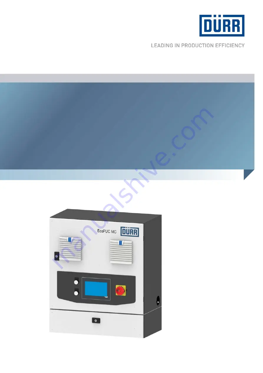
EcoPUC MCElectrical Pump Control System
MCU00003EN, V03
F30400001V
www.durr.com
Operation manual
Page 1: ...EcoPUC MC Electrical Pump Control System MCU00003EN V03 F30400001V www durr com Operation manual...
Page 2: ...ephone 49 7142 78 0 Internet www durr com Transmission and duplication of this document as well as use and sharing of its contents are not permitted without express written approval Violations will be...
Page 3: ...rations can deviate from the technical con struction Validity range of the document This document describes the products with the fol lowing material numbers F30400001V EcoPUC MC EcoPUC MC Extension A...
Page 4: ...rk area 23 8 4 Menu bar 23 8 5 System settings 23 8 5 1 Overview 23 8 5 2 Reset password 24 8 5 3 Change password 24 8 5 4 Screen cleaning 25 8 5 5 USB functions 25 8 5 6 Log on and Log off 25 8 5 7 S...
Page 5: ...12 Replacement parts tools and accesso ries 53 12 1 Replacement parts 53 12 2 Tools 53 12 3 Accessories 54 12 4 Order 54 13 Index 55 Appendix 58 A Interfaces 59 05 2017 EcoPUC MC MCU00003EN 5 68...
Page 6: ...structions manual DANGER High risk situation that can lead to serious inju ries or death WARNING Medium risk situation that can lead to serious injuries or death CAUTION Low risk situations that can l...
Page 7: ...the control system within the approved technical data 11 Technical data Mount the control system on the wall or on a base using the provided holes in the control system 5 2 Assembly Wrong use Improper...
Page 8: ...inst reconnection Close material supply lines Relieve the pressure on material lines Secure against reconnection Emergency shutdown Fig 4 Main switch 1 Put the main switch 1 on OFF The control system...
Page 9: ...and Safety Regulations Directives and rules of engineering Applicable accident prevention regulations The system operator is responsible for the fol lowing tasks on equipment and components Operating...
Page 10: ...4 Duct for hoses and cables 5 Electro pneumatic components 6 Connection for base Main cabinet and extension cabinet rear view Fig 7 Main cabinet and extension cabinet rear view 1 Holes for wall mount...
Page 11: ...9 Proportional valve terminal Extension cabinet Fig 9 Extension cabinet interior view 1 Line filter 2 Frequency inverter 3 Power switch 4 Control for control system fan 5 24 V load monitoring 6 Thermi...
Page 12: ...hes the power supply on or off The switch switches off the system in an emergency situation Controls on the extension cabinet Fig 12 Controls on the extension cabinet 1 Off 2 On Item Operation 1 The i...
Page 13: ...ontrol System Circuit Diagram Base optional ATEX control panel for external operation optional Indicator light for status display optional Inspect delivery on receipt for completeness and integrity Re...
Page 14: ...lectrical voltage present on components and lines Live components are wired with orange lines There is the danger of electrical shock on contact with live components which can cause death Before carry...
Page 15: ...e cabinet Use anchor bolts M 8 Ensure that the cabinet is seated firmly Follow the circuit diagram Applicable docu ments Fig 13 Main cabinet rear side 1 Mark bore holes on the wall Bore distances 550...
Page 16: ...Safety boots 1 Connect the channels 1 and 2 for external emergency stop e g Emergency Stop button 2 Connect the channels 1 and 2 for emergency stop from a higher level control 3 Connect channels 1 an...
Page 17: ...ol system see circuit diagram Connection for feed and external Appli cable documents 6 Commissioning 6 1 Safety recommendations DANGER Danger due to electrical voltage When the supply voltage is switc...
Page 18: ...Operation 7 1 Safety recommendations DANGER Danger due to electrical voltage When the supply voltage is switched off there is electrical voltage present on components and lines Live components are wi...
Page 19: ...on the operator panel Error messages are acknowledged Fig 17 Switching on control system 3 Press On 1 The control system is switched on Switching on extension cabinet Fig 18 Extension cabinet control...
Page 20: ...e and Pro duction mode of the pump Select interval mode only possible in Stand by mode Enable filter maintenance Enable External operating mode External operating mode Process functions are controlled...
Page 21: ...three areas Fig 24 Operator interface 1 Header row 2 Work area 3 Menu bar 8 2 Header row Fig 25 Header row 1 Active mode 2 User level 3 Pumps 1 to 4 4 Language 5 Date and clock time 6 Alarm notificat...
Page 22: ...pump is shown with a green border 3 Exit the window using the button 2 The header row indicates the active pump with a black border Pump status Symbol Color Meaning Gray Switched off Green Stand by m...
Page 23: ...on is only displayed if the values entered are correct 8 4 Menu bar Fig 31 Menu bar 1 System settings 2 Pump settings 3 Parameter management 4 Measured values 5 System monitoring 6 Alarm history 7 Ack...
Page 24: ...ds are reset to factory settings 5 Exit the window again using the button 3 8 5 3 Change password Personnel System operator User level 3 required 1 Open Change password menu using the button Fig 35 Ch...
Page 25: ...are stored in the Flash memory of the control system If the control system must be replaced the setup data can be loaded from the USB data carrier Trace data Measured values are recorded in a CSV fil...
Page 26: ...evel can also be changed through the symbol in the header row 8 2 Header row 8 5 7 Setting Date and Clock Time Personnel System operator Fig 41 Setting Date and Clock Time 1 Tap field 1 The input wind...
Page 27: ...window is opened Fig 46 IP settings PLC interface 9 Adjust IP address to the address range of the parent control only if nec essary Enter IP address and port number 1 10 Tap button 2 IP settings are c...
Page 28: ...gs are saved Touch Display is con nected to PLC Menu of the Touch Display closes 8 5 9 Flow chart of the external interface The following charts are examples for flow charts of the external interface...
Page 29: ...1 activated 4 m_OpP1 Pump 1 ready for operation no fault etc 5 m_StartP1 Start pump 1 6 m_RunP1 Feedback pump 1 running Switching over standby production pump 1 local Fig 54 Switching over standby pr...
Page 30: ...ActSelValueP1 Transmit analog value flow rate in ml min 16 Bit integer 8 5 10 Set language Personnel System operator Fig 57 Set language 1 Tap field 1 The drop down list opens 2 Tap the desired langua...
Page 31: ...tive Production mode is not active Pump is in Stand by mode Tapping starts the Production mode 7 Standby Stand by mode is active Stand by mode is not active Pump is in Production mode Tapping starts t...
Page 32: ...ler Parameter for setting the control pressure for the recirculation controller in Production mode Values between 0 and 5 bar can be parameterized PID parameter P Proportional amplification of the PID...
Page 33: ...trol pressure recirculation controller bar Set control pressure for the recirculation controller in stand by mode Values between 0 and 5 bar can be parameterized Interval mode Operating the pump at in...
Page 34: ...the time parameter and the maximum rotational speed of 80 Hz is exceeded the pump switches off An alarm message appears Pressure control lower pressure threshold bar A warning appears if the bottom p...
Page 35: ...tor 1 Use the button to open the Plant moni toring menu Fig 68 System monitoring 1 Operating hours h 2 Energy consumption Wh 3 Double strokes 4 Reset button Use the button 4 to reset all values of the...
Page 36: ...P74 13 Alarms Drive 2 Alarms B R Converter P84 14 Emergency Stop pump 2 Local Emergency Stop pump 2 15 Buzzing alarm process pump 2 Local process alarms pump 2 16 Buzzer warnings pump 2 Local warning...
Page 37: ...ption 0 General power link error Error in the power link connection to the PLC 1 Powerlink connection Drive 1 Error in the power link connection to the frequency converter of the pump 1 2 Powerlink co...
Page 38: ...p 2 4 24 V fuse Drive 3 Monitoring 24 V fuse Pump 3 5 24 V fuse Drive 4 Monitoring 24 V fuse Pump 4 Alarm group 6 Alarm number Name Description 0 USB Error Error while reading from the USB stick 1 Err...
Page 39: ...EPF1 External error in LT or local connection 9 Frequency converter Overcurrent OCF Over current 10 Frequency converter Precharge CrF Error of the load relay 11 Frequency converter Speed fdback loss S...
Page 40: ...e control bLF 3 phase loss of the brake motor 36 FREE 37 FREE 38 Frequency converter External fault com EPF2 External interruption in the communica tion card 39 FREE 40 FREE 41 Frequency converter Bra...
Page 41: ...1 FREE 62 FREE 63 FREE 64 Frequency converter input contactor LCF Line contactor error 65 FREE 66 Frequency converter Diff I fault dCF Error in differential current 67 Frequency converter IGBT desatur...
Page 42: ...nderload Flt ULF Speed underload 101 FREE 102 FREE 103 FREE 104 FREE 105 Frequency converter Angle error ASF Error in pulse wheel setting detected 106 FREE 107 Frequency converter Safety fault SAFF Tr...
Page 43: ...riggering of maximum pressure gov ernor Pump 1 2 3 4 2 Emergency Stop pump 1 2 3 4 External emergency stop emergency stop triggered from external or fire protec tion pump 1 2 3 4 Alarm groups 10 15 20...
Page 44: ...r of pump 1 2 3 4 at 100 12 FREE 13 FREE 14 FREE 15 FREE 16 FREE 17 FREE 18 FREE 19 FREE 20 Service interval 1 pump 1 2 3 4 due Service interval every 1000 operating hours 21 Service interval 2 pump 1...
Page 45: ...ht damage the hearing Before carrying out any work Depressurize pneumatic lines Wear ear protection WARNING Risk of injury from unsuitable replacement parts Parts of third party suppliers may not bear...
Page 46: ...n module 9 3 2 2 Replace the illumination module 9 3 2 Maintenance work 9 3 2 1 Replace compressed air hoses Personnel Mechanic Protective equipment Eye protection Use ear protection Protective workwe...
Page 47: ...are allowed to work on control system electrical lines and components WARNING Danger from noise Disconnecting pressurized pneumatic lines cre ates loud noises This might damage the hearing Before carr...
Page 48: ...power supply 3 Verify no current is present 10 2 2 Disconnect grounding Personnel Qualified electrician Protective equipment Protective workwear Protective gloves Safety boots Fig 71 Grounding bolt in...
Page 49: ...n and cause serious injuries or death Do not enter the area below hovering loads Wear specified protective equipment Only use approved hoists and stoppers Ensure that the hoists and stoppers have adeq...
Page 50: ...according to the disposal provisions in force In case of doubt refer to the local disposal authorities Personnel Mechanic Protective equipment Protective workwear Protective gloves Safety boots 1 Cle...
Page 51: ...quency 50 60 Hz Power Option Value EcoPUC MC X 0750 XX X X X 2 3 kVA EcoPUC MC X 1500 XX X X X 4 2 kVA EcoPUC MC X 3000 XX X X X 7 3 kVA Power Option Value EcoPUC MC X 0750 XX X X X 3 3 A at 3 x 400 V...
Page 52: ...min 4 mA Electrical current strength max 20 mA Scaling pressure sensor min 0 bar Scaling pressure sensor max 25 bar Isolating switch amplifier digital with lead break detection for maximum pressure g...
Page 53: ...ent monitoring feed set E18260002 Denomination Material number Current monitoring 24 V DC E18260003 Thermistor motor pro tective conductor dos imeter E44010008 Filter fans F10030030 Outlet filter N350...
Page 54: ...2 OEL FLEX E09130033 Thermistor motor protective conductor 3 x 1 mm2 OELFLEX E09130024 Connecting cable with M 9 Plug 2 x 0 5 mm2 50 m BLUE E09060639 Base N29090130 12 4 Order WARNING Risk of injury f...
Page 55: ...8 Contact 3 Control system connect to ground 16 D Data charging 25 securing 25 Date adjustment 26 Depth 50 Dimensions 50 disassembly Extension cabinet 49 Main cabinet 49 Disassembly Base 50 Dismantli...
Page 56: ...ions 18 Operator interface Overview 21 Operator Interface Header row 21 Operator panel Main cabinet 12 Order 54 Overview Product 6 P Packaging Handling packaging material 13 Parameter adjustment 32 33...
Page 57: ...Interfaces 52 Operating conditions 51 Technical Data Connections 7 Tools 53 Touch display Setting IP address 26 Training 9 Transport Inspection 13 Type plate 51 U UDP interface activation 26 USB func...
Page 58: ...Appendix 05 2017 EcoPUC MC MCU00003EN 58 68...
Page 59: ...INT iSpare_10 Spare 12 0 INT iSpare_12 Spare 14 0 INT iSpare_14 Spare 16 0 INT iSpare_16 Spare 18 0 INT iSpare_18 Spare 20 0 BOOL m_StOn Station ON 20 1 BOOL m_StExtMode Station External Mode 20 2 BO...
Page 60: ...Return Valve Pump 3 40 0 INT i_ActFwdPresP4 Forward Pressure Pump 4 42 0 INT i_ActSelValueP4 Actual Motor Frequency or Delivery Rate Pump 4 44 0 INT i_ActRetPresP4 Actual Control Pressure Return Valv...
Page 61: ...ternal Mode External TRUE 64 2 BOOL m_OpP3 Operative Pump 3 Operative TRUE 64 3 BOOL m_RunP3 Run Pump 3 RUN TRUE 64 4 BOOL m_AckModeP3 Mode Pump 3 Standby FALSE Production TRUE 64 5 BOOL m_AckIntModeP...
Page 62: ...e_14 Spare 16 0 INT iSpare_16 Spare 18 0 INT iSpare_18 Spare 20 0 BOOL m_relStOn Release switch on EcoPUC from main statio 20 1 BOOL m_AckFault Error acknowledge 20 2 BOOL m_TimeSync Set date and time...
Page 63: ...re 56 0 INT iSpare_56 Spare 58 0 INT iSpare_58 Spare 60 0 INT iSpare_60 Spare 62 0 BOOL m_RelStOnP1 Release Station Pump 1 On 62 1 BOOL mSpare_62_1 Spare 62 2 BOOL m_StartP1 Start Stop Pump 1 62 3 BOO...
Page 64: ...5 BOOL m_SelectActValueP3 Select Motor Frequency or Delivery Rate Pump 3 64 6 BOOL mSpare_64_6 Spare 64 7 BOOL mSpare_64_7 Spare 65 0 BOOL m_RelStOnP4 Release Station Pump 4 On 65 1 BOOL mSpare_65_1...
Page 65: ...Bus alarm CAN PWL etc 3 Desk alarm Emergency stop fuse etc 4 Spare 5 Spare 6 Global Warnings Global Warnings e g USB 7 Spare 8 Spare 9 Spare 10 Spare 11 Spare 12 Spare 13 Spare 14 Spare 15 Spare i_Fau...
Page 66: ...s P2 Process alarm pump 2 7 Warnings P2 Warnings Pump 2 8 Drive Alarms P3 Drive alarm pump 3 9 Emergency Stop P3 Emergency Stop Pump 3 10 Process Alarms P3 Process alarm pump 3 11 Warnings P3 Warnings...
Page 67: ...05 2017 EcoPUC MC MCU00003EN 67 68...
Page 68: ...urr com Transmission and duplication of this document as well as use and sharing of its contents are not permitted without express written approval Violations will be liable for compensation for damag...