58
ED100LE
02-2021
DL4616-001
dormakaba ED100 low energy operator – Fine cover
Installation Instructions
Appendix A
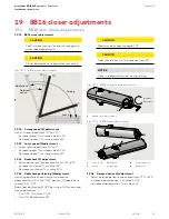
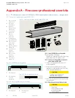
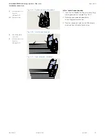
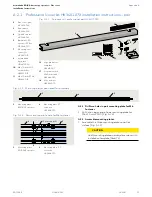
Fig. A.2.4 Mounting plate connectors and fasteners
4
Mounting plate
extr connector
HC3491-010
5
ED100LE operator
mounting plate
4
4
8
8
9
9
6
5
5
6
Backplate, ED
operator FC Ext
HC3468-010
8
M6 x 10 mm SHS
with washer
DF3495-01Z
9
M6 x 10 mm PFHS
DF3496-01Z
4
8
9
2. Secure the operator mounting plates to the pair
mounting plate (
6
) using:
• (2) mounting plate connectors (
4
)
• (2) M6 x 10 mm SHS with washer (
8
)
• (2) M6 x 10 mm PFHS (
9
)
Do not tighten screws.
A.2.3 Check cover fit over ED operators.
1. Place the ED operators onto their mounting plates
(Para. )
2. Place end caps (2) at end of each operator.
3. Place cover over end caps and ED100LE operator.
4. Adjust mounting plates as necessary for cover fit
over end caps.
5. Remove end caps and operators.
6. Tighten mounting plate connector fasteners.
A.2.4 Mounting plate installation.
1. Reference Para. 8.4.
A.2.5 Install program switch.
1. Once header is installed, single program switch must
be installed in fine cover end cap opposite the power
switch.
2. Program switch wires to the active door operator
(Fig. A.2.6).
A.2.6 Install Service Call label in cover.
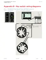
1. Install Service Call label (Fig. A.2.7) on inside of cover.
• Service call label included in Low Energy label kit
HK3137-030.
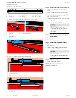
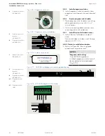
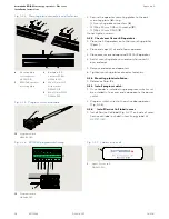
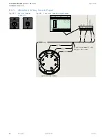
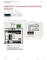
Fig. A.2.6 ED100LE program switch wiring
13
Fig. A.2.5 Program switch and cable
13
Program switch
HX3486-030
30 31 32
33
34
3 35 3
Br
own
Gr
een
Whit
e
X1
13
Yello
w
13
Program switch
HX3486-030
1
Label, Service call,
DD3425-010
1
Fig. A.2.7 Label, service call

