background image

25

ED100LE

02-2021

DL4616-001

dormakaba ED100LE operator – Fine cover
Installation Instructions

Chapter 8

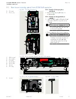
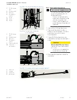
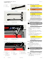
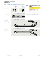
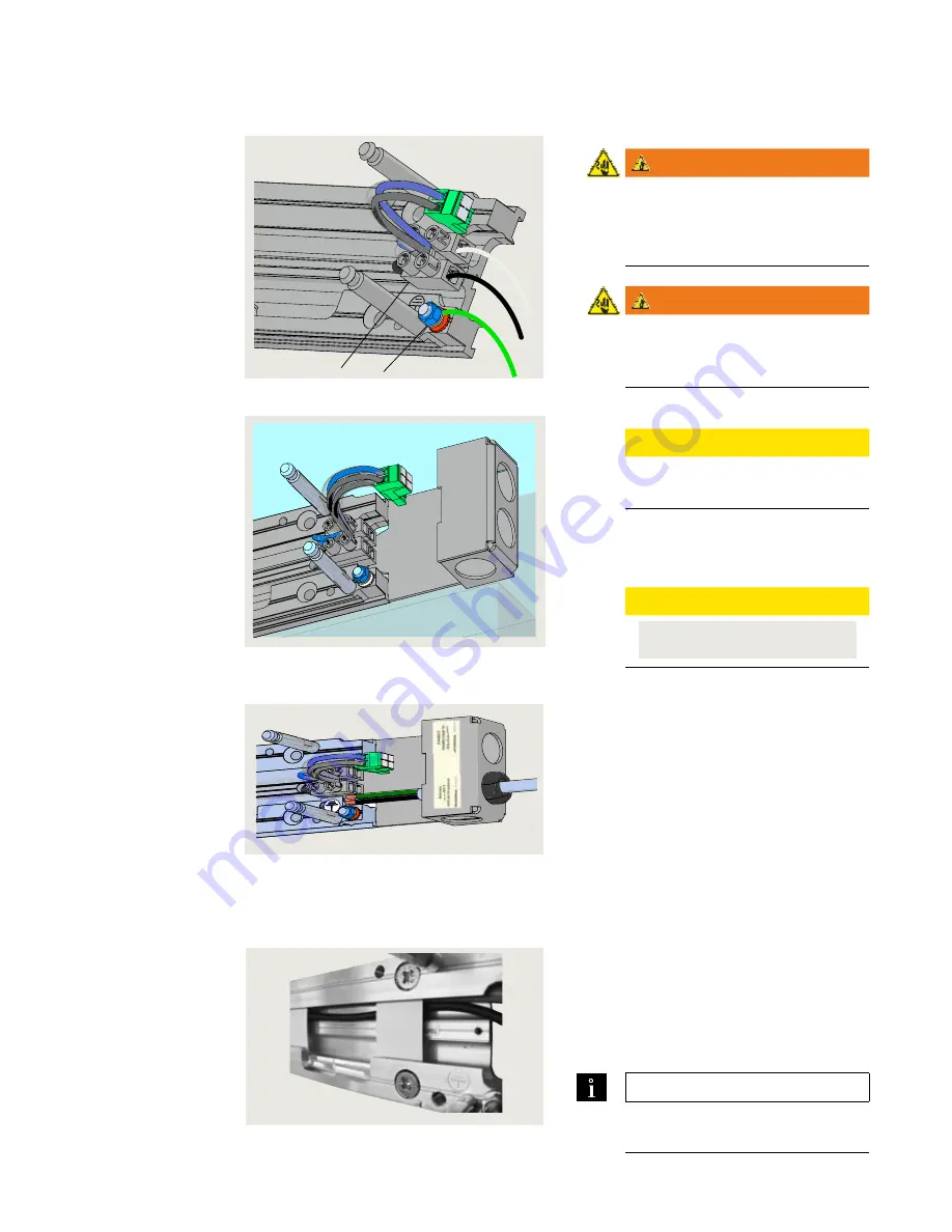
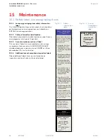
8.5.1  Connect customer 115 Vac wiring.

WARNING

Work on electrical equipment and 
ED100LE 115 Vac wiring 
installation must be only be 
performed by qualified personnel

!

WARNING

Insure disconnect supplying power 
to ED100LE operator is OFF 
before connecting power!

1.  Route wiring to 115 Vac terminal block. 

CAUTION

115 Vac wiring.

Use copper conductors only!

2.  Connect 115 Vac wiring to terminal 

block.

•  Terminal block screw tightening torque.

CAUTION

TIGHTEN MAINS TERMINAL TO 5-7 in-lb 

Use Copper Conductors ONLY

3.  Connect earth ground to ground post.

115 Vac terminal block

5


Ground post

Fig. 8.5.1  115 Vac wiring example

4

5

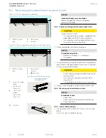
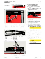
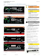
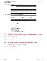
Fig. 8.6.1  Mounting plate slots for 

accessory wiring

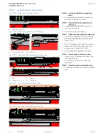
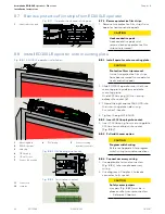
Fig. 8.5.2  Conduit box installation

8.5  Connect customer 115 Vac to mounting plate terminal block

8.6.1 

Route accessory wiring to mounting 
plate.

1.  Route wiring to 115 Vac terminal block 

side of mounting plate (Fig. 8.5.1).

2.  Accessory wiring opposite door hinge 

side: route wiring into mounting plate 
track (Fig. 8.6.1) to  115 Vac terminal 
block side of mounting plate.

TIPS AND RECOMMENDATIONS

Accessory wiring will terminate at 
ED100LE terminal board (Chapter 4).

8.6  Route accessory wiring to mounting plate

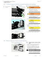
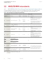
Fig. 8.5.3  PC power cord, conduit box 

installation

Summary of Contents for ED 100 LE

Page 1: ...ED100LE Low Energy Swing Door Operator Fine cover Installation Instructions DL4616 001 02 2021 EN ...

Page 2: ...allation 27 Table of contents 10 Pull arm installation 30 10 1 Pull arm installation 30 10 2 Pull arm assemblies 30 10 3 Pull arm hardware 30 10 4 Install hardware into track 31 10 5 Assemble slide shoe 31 10 6 Assemble drive arm and CPD lever 32 10 7 Fasten drive arm to ED100LE operator 33 10 8 Install track assembly 34 11 ED100LE Operator spring tension 35 11 1 Set operator spring tension 35 12 ...

Page 3: ...om website Manuals are available for review download and printing on the dormakaba com us website 1 1 3 Dimensions Unless otherwise specified all dimensions are given in both inches and mm 1 1 4 Building codes and standards ED100LE installation observe applicable national and local building codes 1 General information 1 1 General information 1 1 5 Symbols used in these instructions WARNING This sy...

Page 4: ...push Fig 1 2 2 LH pull Fig 1 2 3 LH pull as a push 1 2 Single door configuration examples Fig 1 3 1 Push 1 3 Double door configuration examples Fig 1 3 2 Pull Fig 1 3 3 Pull as push track mount installation Fig 1 3 4 Double egress Fig 1 3 5 Companion door push without cover Fig 1 3 6 Companion door pull without cover ...

Page 5: ... 3 Doorshouldcloseataslow smoothpace 4ormore seconds andstopwithout impact 4 Inspectthefloorarea It shouldbecleanwithno loosepartsthatmightcause usertotriporfall Keep trafficpathclear 5 Inspect door s overall condition Theappropriate signageshouldbepresent andthe hardware should be in good condition 6 Havedoorinspectedbyan AAADMcertifiedinspector at least annually AAADM American Association of Aut...

Page 6: ...sh arm door stop option Fig 2 4 1 Door stop assembly HS4633 001 2 1 4 thick base plate DC4633 001 3 Rubber bumper DC4633 003 4 Shoulder screw DC4633 004 5 1 1 4 x 1 1 4 Phillips FHS black oxide SS 5 2 No 14 x 1 1 4 Phillips FHS for sheet metal zinc plated steel Fig 2 4 2 Mounting screw kit HC4633 005 2 3 4 5 1 5 2 2 5 Fine cover kit basic 2 5 1 Fine cover kit basic HK3401 01X 4 3 11 15 3 Fine cove...

Page 7: ...pair HK3401 07X 2 6 Fine cover professional cover kits option Fig 2 6 1 Fine cover kit professional single HK3401 05X 1 Fine cover single HC3459 01X 3 End cap set HC3466 01X 4 Backplate ED oper FC Ext HC3468 010 6 Cover bracket HC3481 010 7 Mtg extr connector HC3491 010 9 dormakaba logo plate HD4613 010 10 M6 x 10 mm SHS with washer DF3495 01Z 11 M6 x 10 mm PFHS HF3496 01Z 13 Logo placement templa...

Page 8: ...screw kit HK2719 020 10 1 10 2 9 1 9 2 2 8 Deep pull arm kit 2 9 Arm screw kits Fig 2 8 1 Deep pull arm kit HK4709 12X 1 Deep pull arm DC4678 02X 3 Screw kit HK2719 020 1 3 3 2 Key switch panel RJ45 HX4604 21C 3 Key switch panel HX4604 11C Fig 2 10 1 Key switch panels 2 2 10 Optional key switch panels 9 1 10 24 x 1 1 2 barrel nut DF2718 01Z 9 2 10 24 x 1 2 PPHMS DF3278 01Z 10 1 10 24 x 1 1 2 barre...

Page 9: ...andard Operator weight 21 8 lb 9 9 kg Power supply for accessories 24 Vdc 5 1 5 A Maximum door opening angle 95 to 110 depending on installation type 3 1 3 Inputs Wire size Connector plug screw size 14 AWG 1 16 Activation inputs X4 Interior exterior N O contact Safety sensors X5 Swing approach sides Night bank intercom system X10 57 57a 8 24 Vdc Vac 5 Night bank key switch X1 35 3 d2 parameter Con...

Page 10: ...ypad 2 digit display Slot for upgrade cards Extension of functional range Firmware update Firmware update TMP temperature management program Overload protection IDC initial drive control Driving phase optimization Cycle counter CC parameter 0 to 1 000 000 Power assist function hA hF hS parameters Drive support for manual opening of door Push go function PG parameter Auto opening of door at 4 open ...

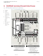
Page 11: ...been commissioned and learning cycle performed Setup and Troubleshooting Manual 4 E100LE terminal board interfaces 97 98 99 30 31 32 34 33 3 3 35 1 3 6 1 4 4a 3 B A 1 57 57a 1 42 3 1 41 3 1 15 17 3 1 11 13 3 43 3 64 63 62 1G 3 24 V Signal input 0 V Partial Open Permanent Open Exit Only Automatic Off N C COM Test output X5 X4 X3 X6 X9 X1 X7 24 V X8 0 V X10 8 24 AC DC 5 Wet DCW bus Activation inputs...

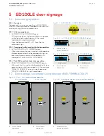
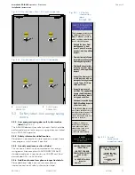
Page 12: ...Push Pull used to initiate door operation 1 PUSH TO OPERATE PULL TO OPERATE decals When push pull is used to initiate operation of door operator doors shall be provided with the message PUSH TO OPERATE on push side of door and PULL TO OPERATE on pull side of door DD0758 010 DD0762 010 DD0762 020 CAUTION DOOR AUTOMATIC DD0586 010 DD0586 010 1 Activate Switch to Operate DD0758 010 DD0758 010 ACTIVAT...

Page 13: ...ition to those in the Owner s Manual should be made each day and after any loss of electrical power Fig 5 3 1 LE Safety information label DD1269 040 5 3 Safety label low energy swing doors 5 3 1 Low energy swinging door safety information label Fig 5 3 1 This AAADM label outlines safety checks that should be performed daily on low energy swinging door controlled by an ED100LE operator 5 3 2 Safety...

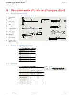
Page 14: ...que wrench 3 to 50 ft lb min 6 1 Metric hex key sockets 7 Open end wrench 13 mm 8 Screwdriver flat blade M2 1 16 to 3 32 Fastener size ft lb M5 3 7 M6 7 M8 17 M10 34 M12 58 6 2 Standard tightening torque 6 2 1 Standard tightening torque Fastener Drill bit size 10 wood screw Hardwood 9 64 Softwood 1 8 12 wood screw Hardwood 5 32 Softwood 9 64 14 wood screw Hardwood 11 64 Softwood 5 32 1 4 20 metal ...

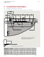
Page 15: ... 3 4 20 2 51 3 7 32 82 1 21 32 42 2 7 8 73 2 3 8 60 3 9 16 91 4 13 16 122 3 7 32 82 4 7 16 113 B D A C Reveal depth maximum 2 3 8 60 Upper edge door Upper edge door Space for cable feed 5 7 8 150 4 3 16 106 1 3 4 45 1 1 4 32 3 15 16 100 1 3 4 45 4 3 4 120 4 3 4 120 4 3 4 120 3 3 4 95 7 11 16 195 Ø 1 4 6 6 2 1 2 63 17 3 4 451 1 1 4 31 1 8 3 When CPD lever is used about 1 3 16 30 must be deducted fr...

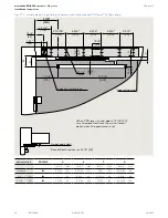
Page 16: ...91 5 5 16 135 3 7 32 82 4 31 32 126 Fig 7 1 2 Assembly on hinge side pull version with slide channel CPD and 1 50 pivot pin B D A C Upper edge door Upper edge door Space for cable feed 5 7 8 150 4 3 16 106 1 3 4 45 1 1 4 32 3 15 16 100 2 1 2 63 4 3 4 120 4 3 4 120 4 3 4 120 3 3 4 95 1 3 4 45 Ø 1 4 6 6 17 3 4 451 1 8 3 1 3 4 44 When CPD lever is used about 1 3 16 30 must be deducted from the actual...

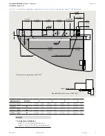
Page 17: ...9 16 65 3 15 16 100 Fig 7 1 3 Assembly on opposite hinge side push version with slide channel and 1 2 25 pivot pin B D A C Lower edge frame Lower edge frame Space for cable feed Reveal depth maximum 2 3 8 60 The maximum opening width is 95 5 7 8 150 4 3 16 106 1 3 4 45 1 1 4 32 3 15 16 100 4 3 4 120 4 3 4 120 4 3 4 120 3 3 4 95 Ø 1 4 6 6 17 3 4 451 5 11 16 145 1 3 8 35 2 1 2 63 1 3 4 45 NOTICE 1 i...

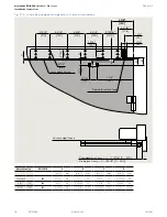
Page 18: ...1 1 2 38 2 13 16 71 1 1 8 29 2 7 16 62 2 3 8 60 3 1 16 78 4 3 8 111 2 23 32 69 4 102 Fig 7 1 4 Assembly on opposite hinge side with push arm assembly B D C A Lower edge frame Lower edge frame Space for cable feed 5 7 8 150 4 3 16 106 1 3 4 45 1 1 4 32 3 15 16 100 9 5 8 245 Ø 1 4 6 6 1 5 16 33 1 31 32 50 4 3 4 120 4 3 4 120 4 3 4 120 3 3 4 95 1 3 4 45 2 1 2 63 Standard push arm 0 11 13 16 0 300 Dee...

Page 19: ... 71 1 1 8 29 2 7 16 62 2 3 8 60 3 1 16 78 4 3 8 111 2 23 32 69 4 102 Fig 7 1 5 Assembly on opposite hinge side with deep push arm assembly B D C A Lower edge frame Lower edge frame Standard push arm 0 11 13 16 0 300 mm Space for cable feed Note lever position 1 1 4 32 9 7 8 250 8 1 8 206 3 15 16 100 4 3 4 120 4 3 4 120 4 3 4 120 3 3 4 95 2 1 2 63 1 3 4 45 Ø 1 4 6 6 1 5 16 33 1 31 32 50 12 13 16 32...

Page 20: ...for the door TIPS AND RECOMMENDATIONS Knowing act device wiring should be planned for prior to operator installation 8 1 3 ED100LE mounting plate installation preparation CAUTION Using applicable ED100LE installation template Chapter 7 holes for mounting plate fasteners must be located and drilled into door frame wall or substructure prior to mounting plate installation CAUTION Mounting plate inst...

Page 21: ...t head cap screws SHCS using a 5 mm hex T handle TIPS AND RECOMMENDATIONS Insure all eight fasteners are free of the mounting plate 2 Remove operator from mounting plate TIPS AND RECOMMENDATIONS Guide pin resistance may require screwdriver to start operator removal from end of mounting plate Fig 8 2 3 Fig 8 2 1 115 Vac plug removal Fig 8 2 3 Mounting plate removal Fig 8 2 4 5mmT handle hexkey 5 Gu...

Page 22: ...ion 2 Power cord wiring kit PC Fig 8 3 4 Eliminates need for hard wiring Permits ED100LE to plug directly into 115 Vac receptacle Power cord length 15 from end of conduit box to center of plug CAUTION Insure PC installation conforms to local and national electrical codes 1 115 VAC terminal block 2 Ground terminal 3 Mains terminal torque and wire label 5 M3 5 screw 6 115 Vac plug to operator L 115 ...

Page 23: ...ate 3 Thread M3 Phillips head screw into conduit box mounting hole and tighten screw CAUTION Terminal block M3 screw torque Tighten M3 screw to a torque of 5 7 in lb Insure screw is threaded into conduit box mounting hole 4 Mounting plate assembly is ready for installation Fig 8 3 5 115 Vac terminal block mounting Fig 8 3 6 Conduit box installed on mounting plate 1 115 VAC terminal block 2 Ground ...

Page 24: ...asteners based on door frame and wall material Use fasteners provided with ED100LE Fig 8 4 3 Use appropriate wall anchors if required 3 Fasten mounting plate to door frame and or wall 8 4 2 Mounting plate installation checks NOTICE Installation checks Check level Check spindle to hinge centerline distance Check alignment 8 4 3 Install third guide pin 1 Install third guide pin Fig 8 4 1 8 4 4 in mo...

Page 25: ...TERMINAL TO 5 7 in lb Use Copper Conductors ONLY 3 Connect earth ground to ground post 4 115Vacterminalblock 5 Groundpost Fig 8 5 1 115 Vac wiring example 4 5 Fig 8 6 1 Mounting plate slots for accessory wiring Fig 8 5 2 Conduit box installation 8 5 Connect customer 115 Vac to mounting plate terminal block 8 6 1 Route accessory wiring to mounting plate 1 Route wiring to 115 Vac terminal block side...
Page 26: ...ac plug into socket 1 Insert 115 Vac plug from mounting plate 115 Vac terminal block into socket Fig 8 8 2 8 8 3 Full width cover option CAUTION Program switch wiring Reference Appendix A for program switch wiring terminal connections 8 8 4 Connect accessory wiring 1 Use applicable terminal connectors Fig 8 8 3 to terminate accessory wiring 2 Use diagram in Chapter 4 to locate connector to its soc...

Page 27: ...1 1 4 285 5 Adjustment arm tube 12 1 4 311 6 Shoe 7 M6 x 10 mm flanged button head screw 8 Ball head 11 Shoe screw cover 12 M8 x ___ SHCS 13 Cap Fig 9 2 2 Splined push arm assembly 19 11 16 500 DC4677 02X 1 Splined drive arm 2 Socket 6 Shoe 7 M6 x 10 mm flanged button head screw 8 Ball head 9 Adjustment arm 17 3 4 450 10 Adjustment arm tube 17 3 4 450 11 Shoe screw cover 12 M8 x ___ SHCS 13 Cap 9 ...

Page 28: ...ve arm and axle extension Thread SHCS into ED100LE spindle and tighten CAUTION Use torque wrench with hex key socket to tighten SHCS to 17 ft lb 23 Nm 9 2 3 Drill two holes in door for adjustment arm shoe Installation templates Chapter 7 document location of shoe on door 1 Drill two holes in door for adjustment arm shoe Fastener type based on door material TIPS AND RECOMMENDATIONS Reference Chapte...

Page 29: ...o M6 x 10 mm flanged button head screws CAUTION Recheck that adjustment arm is at 90 angle to door 1 Drive Arm 2 Socket 4 Adjustment arm 11 1 4 285 5 Adjustment arm tube 12 1 4 311 6 Shoe 7 M6 x 10 mm flanged Fig 9 2 8 Arm assemblies attached to door ED100LE button head screw 8 Ball head 9 Adjustment arm 17 3 4 450 Fig 9 2 10 Adjustment arm at 900 angle to door 1 Drive Arm 5 Adjustment arm tube 12...

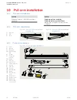
Page 30: ...hoe 10 Pivot pin 11 Retaining ring 12 Bumper 13 M8 x 1 25 x 40 SHCS 14 Wood screws 15 Machine screws 16 Bumper stop 17 M5 x 13 FHMS cross recessed Fig 10 3 1 Pull arm assembly HK4709 12X Fig 10 2 1 Arm with CPD lever and track assembly LH 1 Drive arm 2 CPD 3 Track Fig 10 2 2 Arm with CPD lever and track assembly RH 1 2 3 3 1 4 2 3 3 1 5 5 1 6 7 8 9 10 11 12 13 14 16 17 NOTICE Reference Chapter 7 E...

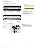
Page 31: ...g piece to end of track with M5 x 15 screw 3 1 Use No 2 Phillips do not over tighten Fig 10 4 1 RH track assembly 1 Track 3 Fixing piece 9 Slide shoe 12 Bumper Fig 10 4 2 LH track assembly 1 Track 3 Fixing piece 9 Slide shoe 12 Bumper 16 Bumper stop 17 M5 x 13 FHMS cross recessed 1 9 12 3 3 1 2 2 16 17 3 3 12 9 1 2 2 16 17 16 Bumper stop 17 M5 x 13 FHMS cross recessed 10 5 Assemble slide shoe Fig ...

Page 32: ...ns into corresponding holes in arm 2 Secure CPD lever to arm with M6 x 10 SHCS Fig 10 6 5 Arm assembly LH pull RH push Fig 10 6 4 Arm assembly RH pull LH push 4 CPD lever 4 1 M6 x 10 SHCS 7 Slotted spring pin 16 Arm 7 6 1 M6 x 10 SHCS 7 Slotted spring pin Fig 10 6 1 Slotted spring pin Fig 10 6 3 CPD lever and slotted spring pins 6 CPD lever 7 Slotted spring pin 7 6 4 CPD lever 4 1 M6 x 10 SHCS 7 S...

Page 33: ...r spring tension 2 Turn spring preload back to zero rotations fully CCW 3 Push the drive arm onto the spindle at an angle of approximately 12 to the ED100LE operator Fig 10 7 1 4 Rotate drive arm spindle approximately 10 in door s opening direction Fig 10 7 2 5 Remove the drive arm from spindle Fig 10 7 3 6 Position the drive arm with axle extension one tooth in door s closing direction Fig 10 7 4...

Page 34: ...embled based on hand of door Para 10 4 2 With fixing piece removed from track on opposite end from bumper slide track assembly onto shoe Fig 10 8 3 3 Install second fixing piece onto track 10 8 4 Secure track assembly to door 1 Attach track fixing pieces to door using selected fasteners Insure track is level as fasteners are tightened 10 8 5 Install end caps and spindle caps 1 Install two end caps...

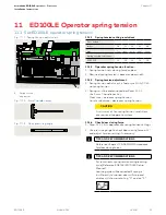
Page 35: ...ases spring tension Counterclockwise decreases spring tension CAUTION A minimum of ten spring tension revolutions are required to operate system 11 1 4 Check door closing force 1 Para 11 1 1 lists approximate spring tension settings 2 Use pressure gauge to check door closing force at 2 and adjust tension setting if necessary TIPS AND RECOMMENDATIONS Reference Chapter 12 ANSI BHMA standards for doo...

Page 36: ...s 30s 4 3 Timedelay Whenpoweredopen thedoorshallremain openatthefullyopenedpositionfornotless than5seconds Exception whenpush pullactivationisused thedoorshallremainatthefullyopened positionfornotlessthan3seconds hS Supportformanualmodein doorclosedposition 4 5 hA Adjustment dooractivation angle hF Powerassistfunction Fo Static force in opening direction Staticforceondoorclosing edgeinopeningdirec...

Page 37: ...1s Ifdooropensmorethan90 itshallcontinueatthesamerateasbackcheckspeed Backcheckoccurringatapointbetweenpositionsshalluselowestsetting 12 1 4 Other door weights and widths Closing time T D W 188 D Width of door in inches W Weight of door in pounds T Closing time to latch check in seconds SI metric units Closing time T D W 2260 D Width of door in mm W Weight of door in kg T Closing time to latch che...

Page 38: ...w Energy Swinging Doors 1 Activatethedoor Door shouldopenat a slow smooth pace 4 or more seconds andstopwithout impact 2 Doormustremainfullyopen foraminimumof5seconds beforebeginningtoclose 3 Doorshouldcloseataslow smooth pace 4 or more seconds andstopwithout impact 4 Inspectthefloorarea It shouldbecleanwithno loosepartsthatmightcause usertotriporfall Keep trafficpathclear 5 Inspect door s overall...

Page 39: ...e arm M8 SHCS torque 1 Set program switch to CLOSE 2 Remove cap over M8 SHCS 3 Check torque 4 Replace cap CAUTION Using torque wrench with 6 mm hex key socket check M8 SHCS torque 17 ft lb 23 Nm 15 2 2 Check pivot pin M8 socket head torque 1 Check torque CAUTION Use torque wrench with hex key socket M8 screw torque 5 9 7 4 ft lb 8 10 Nm Fig 15 2 3 Pivot pin M8 socket head 3 Pivot pin M8 socket hea...

Page 40: ...h centerline of hinge pin 1 1 8 28 5 Cover and axle end are fixed and cannot be extended Track height from bottom of cover 1 1 4 31 7 with 1 2 12 pivot pin 1 5 8 41 3 with 1 25 pivot pin Track height from bottom of cover 1 1 2 38 1 with 1 2 12 pivot pin 2 50 8 with 1 25 pivot pin Section A A Operator side Section B B Closer side Reveal 0 2 1 4 57 5 1 8 129 Axle distance Bottom of arm aligns to bot...

Page 41: ...From edge of door 1 15 16 50 Centerline of hinge pin B B Axle centerline 8 9 16 216 70 9 16 13 50 FIXED 12 3 4 324 64 From edge of door 1 15 16 50 Centerline of hinge pin Arm clearance bottom of operator 2 3 4 70 5 1 16 129 Shoe height bottom of operator Reveal 0 8 3 4 222 Section B B Closer side Reveal 0 8 3 4 222 5 1 16 129 Arm clearance bottom of operator 2 3 4 70 Shoe height bottom of operator...

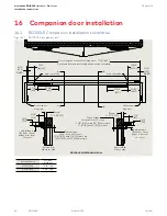
Page 42: ...ll advance approximately 150 4 Backcheck positioning Adjustable Adjustable hydraulic backcheck will take effect at approximately 700 3 DEL Delayed action Adjustable Delays door closing to allow unobstructed passage through the opening 16 2 1 Companion door 8616 Door closer data 16 2 1 1 8816 adjustments 1 2 3 4 8 5 8 6 8 4 2 Fig 16 2 3 Companion closer adapter HC3468 070 2 Companion closer adaptor...

Page 43: ... 3 M6 x 10 mm Phillips flat head screw DF3496 01Z 1 2 3 Fig 16 4 1 Backplate connect kit HK3491 001 Fig 16 4 2 Backplate assembly example 16 4 1 Remove ED100LE operator from mounting plate 1 Reference Chapter 8 Para 8 2 2 Remove ED100LE operator from its mounting plate 16 4 2 Connect ED100LE mounting plate and closer mounting plate 1 Connect ED100LE operator mounting plate to companion mounting pl...

Page 44: ...er FIXED 17 1 1 Install backplate push arm application 1 Using backplate template Fig 17 1 1 and 17 1 2 locate left hand and right hand backplate mounting holes on door frame wall NOTICE Template documents a LH push installation Template must be mirrored for a RH push installation 2 Place backplate on door frame wall and align with the mounting hole locations in step 1 Check hinge pin centerline t...
Page 45: ...g 17 2 3 Closer adapter and closer assembly mounting to backplate push arm application 3 4 x 1 4 20 x 5 8 Philips flat head screw DF0399 00G 17 2 1 Install 8816 closer for push arm application NOTICE Verify closer spring size prior to installation NOTICE PUSH J mounting holes For push arm application use PUSH J mounting holes Fig 17 2 3 8 4 Fig 17 2 1 Companion screw kit HK4607 001 4 3 Fig 17 2 2 ...
Page 46: ...sion Thread SHCS into 8816 pinion and tighten NOTICE M8 SHCS tightening torque Use torque wrench 25 ft lbs to tighten SHCS to 17 ft lb 23 Nm 17 3 Push arm installation Fig 17 3 1 Drive arm installation 1 Drive arm 2 20 mm axle extension 90 1 2 3 3 20 mm bolt axle extension Fig 17 3 2 Drive axle extensions 1 20 mm axle extension door closer HC4680 001 2 60 mm axle extension door closer HC4680 002 1...
Page 47: ...ve arm 1 Loosen the two adjustment M6 x 10 mm flanged button head screws 1 Using square position adjustment arm assembly at 90 angle to door 2 Adjust length of adjustment arm until drive arm ball head is aligned with adjustment arm socket CAUTION Maintain adjustment arm assembly at a 90 angle to door 3 Insert adjustment arm ball head into drive arm socket 4 Secure adjustment arm position by tighte...

Page 48: ...rline of hinge pin 10 3 4 272 5 9 16 13 5 FIXED 1 25 4 Axle centerline 2 3 16 56 2 1 7 8 48 Centerline of hinge pin 18 1 1 Install backplate pull arm application 1 Using backplate template Fig 18 1 1 and 18 1 2 locate left hand and right hand backplate mounting holes on door frame wall NOTICE Template documents a RH pull installation Template must be mirrored for a LH pull installation 2 Place bac...

Page 49: ...plate pull arm application 18 2 1 Install 8816 closer for pull arm application NOTICE Verify closer spring size prior to installation NOTICE PULL T mounting holes For pull arm application use PULL T mounting holes Fig 18 2 3 18 2 Install 8816 closer on backplate pull arm mounting 3 4 x 1 4 20 x 5 8 Philips flat head screw DF0399 00G 8 4 Fig 18 2 1 Companion screw kit HK4607 001 4 3 Fig 18 2 2 Comp...

Page 50: ...ter 10 Para 10 4 and assemble hardware into track based on RH or LH pull arm installation 18 3 2 Assemble CPD lever to drive arm 1 Reference Chapter 10 Para 10 6 Assemble CPD lever to drive arm based on RH or LH pull arm installation 1 2 3 3 M8 x 40 mm SHCS Fig 18 3 2 Drive axle extensions 2 60 mm axle extension door closer HC4680 002 1 2 1 20 mm axle extension door closer HC4680 001 Fig 18 3 3 Bo...

Page 51: ... with axle extension Fig 18 3 2 onto the 8816 pinion at a minimum angle of 15 degrees 2 Thread M8 x 40 mm SHCS for 20 mm axle extension into 8816 pinion and tighten SHCS NOTICE M8 SHCS tightening torque Use torque wrench 25 ft lbs to tighten SHCS to 17 ft lb 23 Nm 18 3 4 Drill holes in door for track fasteners NOTICE Pull arm installation template Reference Chapter 16 for installation template 1 U...

Page 52: ...oe pivot pin under CPD lever mounting hole 4 Thread pivot pin M8 SHCS into CPD lever mounting hole 5 Use 6 mm hex key to tighten NOTICE M8 SHCS tightening torque Use torque wrench 25 ft lbs to tighten SHCS to 5 9 7 4 ft lb 8 10 Nm 18 3 6 Install track onto slide shoe pivot pin assembly 1 Slide track onto slide shoe 2 Reinstall fixing piece assembly 18 3 7 Attach track assembly to door 1 Rotate tra...

Page 53: ...atch 7 Sweep 70 75 110 Backcheck Delayed action 19 1 2 Sweep speed 1 adjustment Adjust sweep speed from 700 to 100 Increase speed Turn sweep valve CCW Decrease speed Turn sweep valve CW 19 1 3 Latch speed 2 adjustment 1 Adjust latch speed from 100 to 00 Increase speed Turn sweep valve CCW Decrease speed Turn sweep valve CW 19 1 4 Backcheck 3 adjustment 1 Adjust backcheck for door area from 1100 to...

Page 54: ...te extension to door frame or wall A 1 3 Mounting plate installation checks CAUTION Check level Check spindle to hinge centerline distance Check alignment Fig A 1 2 ED100LE mounting plate 1 Mounting plate Fig A 1 3 Mounting plate extension Fig A 1 4 Mounting plate extension installation 1 1 2 1 Mounting plate 2 Mounting plate extension 2 2 Mounting plate extension HC3614 010 Fig A1 1 Fine cover ki...

Page 55: ...0 3 1 Bracket collar 2 Mounting plate extension 3 Professional cover bracket HC3481 010 2 3 Fig A 1 6 Install cover bracket Fig A 1 7 Cover bracket installed A 1 4 Install cover bracket 1 Insert cover bracket collar into mounting plate groove at an angle Fig A1 5 2 Rotate cover bracket parallel to mounting plate extension 3 Position bracket under set of M6 screws and washers at end of extension ...

Page 56: ...side of cover Service call label included in Low Energy label kit HK3137 010 A 1 8 Return to installation chapter 1 Return to Para 8 4 Mounting plate attachment to jamb or wall NOTICE Program switch wiring Once ED100LE operator is installed program switch wires will be connected to terminal board Fig A 1 10 Fig A 1 11 ED100LEinstallationwithmountingplateextension Fig A 1 12 ED100LE programswitchwi...

Page 57: ...a 7 3 6 Mounting plate FC extension HC3468 010 Fig A 2 3 Pair mounting plate hole for M6 fastener 2 5 mm tap drill 6 5 5 Mounting plate ED100LE operator A 2 1 Professional cover kit HK3401 07X installation instructions pair 2 Fine cover pair HC3459 03X 3 End cap set HC3466 01X 4 Spindle cap set HC3466 02X 5 Backplate ED operator FC Ext HC3468 010 7 Mounting extr connector HC3491 010 9 dormakaba lo...

Page 58: ... each operator 3 Place cover over end caps and ED100LE operator 4 Adjust mounting plates as necessary for cover fit over end caps 5 Remove end caps and operators 6 Tighten mounting plate connector fasteners A 2 4 Mounting plate installation 1 Reference Para 8 4 A 2 5 Install program switch 1 Once header is installed single program switch must be installed in fine cover end cap opposite the power s...

Page 59: ...witch panel wiring diagram RED WHT BLK GRN B L K ORG 57 57a X10 X8 X4 X5 X6 15 17 11 3 1 13 3 1 42 3 3 1 1 41 35 33 32 3 30 3 34 31 1 6 3 1 4 4a 99 98 97 3 B A 1 3 43 64 63 62 1G 3 X9 X1 X7 X3 24 0V 0V 24 Swing side 0V 0V Test Signal Approach side Signal Test 24 0V Feedback contact 0V 0V Door status 35 33 32 3 30 3 34 31 X1 0V 0V Off Automatic Exit Only Permanent Open WHT GRN ORG RED BLK 22 AWG st...

Page 60: ...X5 X6 15 17 11 3 1 13 3 1 42 3 3 1 1 41 35 33 32 3 30 3 34 31 1 6 3 1 4 4a 99 98 97 3 B A 1 3 43 64 63 62 1G 3 X9 X1 X7 X3 24 0V 0V 24 Swing side 0V 0V Test Signal Approach side Signal Test 24 0V Feedback contact 0V 0V Door status 35 33 32 3 30 3 34 31 X1 0V 0V Off Automatic Exit Only Permanent Open WHT GRN RED BLK 22 AWG stranded 7 x 30 Length 80 inches AUTO CLOSE OPEN Fig B2 1 2 Key switch panel...

Page 61: ...nowing act switches diagrams Fig C1 1 1 ACTIVATE SWITCH TO OPERATE decal DD0758 010 1 Activate Switch to Operate DD0758 010 DD0758 010 ACTIVATE SWITCH TO OPERATE DD0758 010 1 Fig C1 2 1 ED operator terminal board activation inputs C1 2 Knowing act switch wiring diagram Fig C1 2 2 Knowing act device wiring 1 42 3 1 41 3 0V Signal 24V 0V Signal 24V Interior Exterior Knowing act switch interior Knowi...

Page 62: ...www dormakaba com dormakaba USA Inc 1 Dorma Drive Drawer AC Reamstown PA 17567 USA T 717 336 3881 F 717 336 2106 ...

Reviews: