51
Crane 4000LE
07-2022
RL6002-001
Crane 4000LE Installation Manual
In-ground Motion Assist 360 drive and speed control
Remote control enclosure
Chapter 12
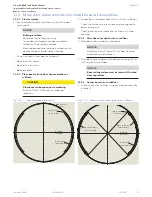
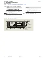
12.9 Check hole alignment of container covers on container flange
TIPS AND RECOMMENDATIONS
It is recommended that steps outlined in
Para. 12.9 be done prior to proceeding with
container installation and assembly.
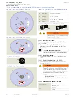
12.9.1 Check fit of center section container lid.
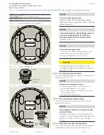
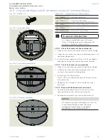
1. Place center section container lid on container flange.
2. Check center section container lid hole alignment with
container flange holes.
3. Install two flat head screws (Fig. 12.9.3) to validate
alignment of all center section container lid holes.
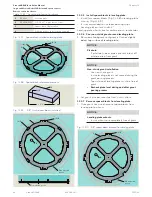
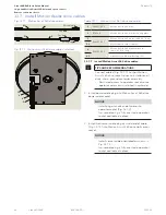
12.9.2 Check fit of outer cover assemblies.
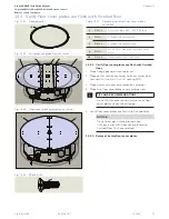
1. Place first outer cover assembly on container flange.
2. Check outer cover assembly hole alignment with
center section container flange holes.
3. Install three flat head screws
(Fig. 12.9.4) to validate alignment of all outer cover
assembly holes.
4. Repeat steps 1 through 3 for second outer cover
assembly.
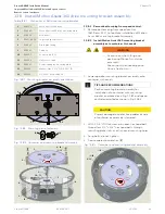
12.9.3 Remove all flat head screws and covers.
1. Remove all flat head screws from the two outer
covers and the center section container lid.
2. Remove covers and center section container lid.
NOTICE
If there are any cover hole alignment issues with
the container flange, contact the Crane
company to resolve these issues before
proceeding with container assembly.
5
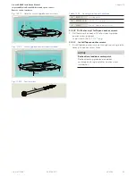
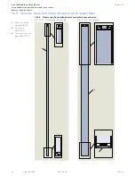
Fig. 12.9.1 RF6025-01G
Fig. 12.9.2 In ground container
Fig. 12.9.3 Center section container lid
Fig. 12.9.4 Outer cover assemblies
1
2
5
5
3
4
4
5
1
RS6038
In-ground container (LP)
2
RC6043
Through-wall pipe fitting.
Fitting may be in a different location
3
RC6049
Center section container lid
4
RX6033
Outer cover assembly
5
RF6025-01G
1/4-20 x 3/4" sealing FHMS
Table 12.9.1
Container covers and fasteners

