


37
Crane 4000LE
07-2022
RL6002-001
Crane 4000LE Installation Manual
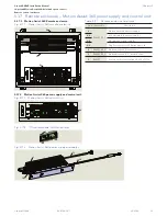
In-ground Motion Assist 360 drive and speed control
Remote control enclosure
Chapter 11
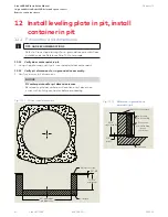
11.2 Mark door base rail locations, install base rail assemblies
11.2.1 Floor
template.
1. Use template to mark the following from the door
centerpoint:
NOTICE
Building interface.
Reference Crane shop drawings.
Insure door centerpoint has been marked in
relation to the building interface.
Base rail locations are marked in relation to the
door centerpoint and building interface.
• Enclosure radius from door centerpoint.
• Base rail outer radius.
• Base rail inner radius.
• Base rail ends.
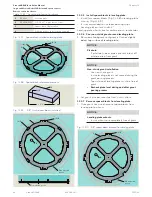
11.2.2 Place base rail and floor clip assemblies on
subfloor.
CAUTION
Place base rail based on post numbering.
Refer to Para. 12.9 for post numbering
locations.
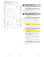
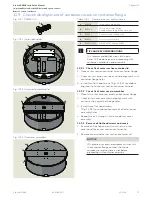
Fig. 11.2.2 Base rail assemblies placed on subfloor
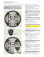
Fig. 11.2.1 Floor template dimensions
Base rail
outer radius
Base rail
inner radius
Enclosure
radius
Building
interface
Base rail
outer radius
Base rail
inner radius
Building
interface
Base rail/base
clip assembly
Base rail/base
clip assembly
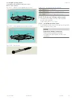
1. Locate base rail assemblies (Fig. 11.3.1) on subfloor.
• Check that base rails are square and are aligned to
door centerpoint.
• Check base rail outer diameter as shown on shop
drawing.
11.2.3 Shim floor clips and fasten to subfloor.
1. Floor base clip installation hardware.
NOTICE
Reference Para. 11.3 and 11.4 for base floor clip
hardware and installation.
2. Shim base rails to obtain top of base rail height flush
with top of finished floor.
NOTICE
Base rail top surface must be level with finished
floor top surface.
11.2.4 Anchor base rails to subfloor.
1. Anchor base clips to floor using concrete anchors (by
installer).


