


43
Crane 4000LE
07-2022
RL6002-001
Crane 4000LE Installation Manual
In-ground Motion Assist 360 drive and speed control
Remote control enclosure
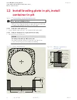
Chapter 12
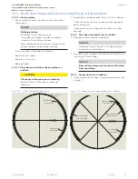
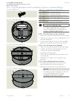
Fig. 12.3.6 Leveling plate in pit example
12.3.2 Check pit dimensions, clean dirt and debris from
pit.
NOTICE
• Pit must be free of all dirt and debris.
• Minimum pit dimensions are shown in
Fig. 12.3.5.
12.3.3 Place leveling plate in pit, locate at door
centerpoint.
NOTICE
• Orient leveling plate parallel to building
interface as shown in Fig. 12.3.6.
• Orientation in pit may be different than
that shown in Fig. 12.3.6.
Leveling plate centerpoint must be positioned
at door centerpoint.
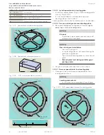
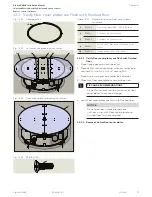
12.3.4 Level and adjust height of leveling plate.
NOTICE
• Adjust four set screws (
2
) to obtain a
leveling plate height (top surface) of
13 3/4" to finish floor line (Fig. 12.3.5).
• Check leveling plate for level.
Recheck that leveling plate is at door
centerpoint and is parallel to building interface
(Fig. 12.3.6).
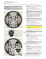
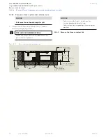
Fig. 12.3.5 Leveling plate installation
1
(4)
2
Pit
Door
centerpoint
c Building
interface
L
3
1/2" REF
9 3/4”
3/8”
Concrete
28” case diameter
32” minimum pit diameter
(4) 1/4” OD x 4” Tapcon concrete screw
(4) 1/2-13 x 2” SS cup-point set screw
1” to 1 1/2” maximum
non-shrinking grout
8 3/4”
minimum
10 3/4”
minimum
Finished floor line
Case height
Leveling plate
Door centerpoint
1
RC6022
Levelling plate
2
RF6028-01G
1/2-13 x 2" cup point set screw
3
Pit drain pipe or tube location example
Table 12.3.2 Leveling plate and hardware


