Square Mode
1
2
3
4
5
6
7
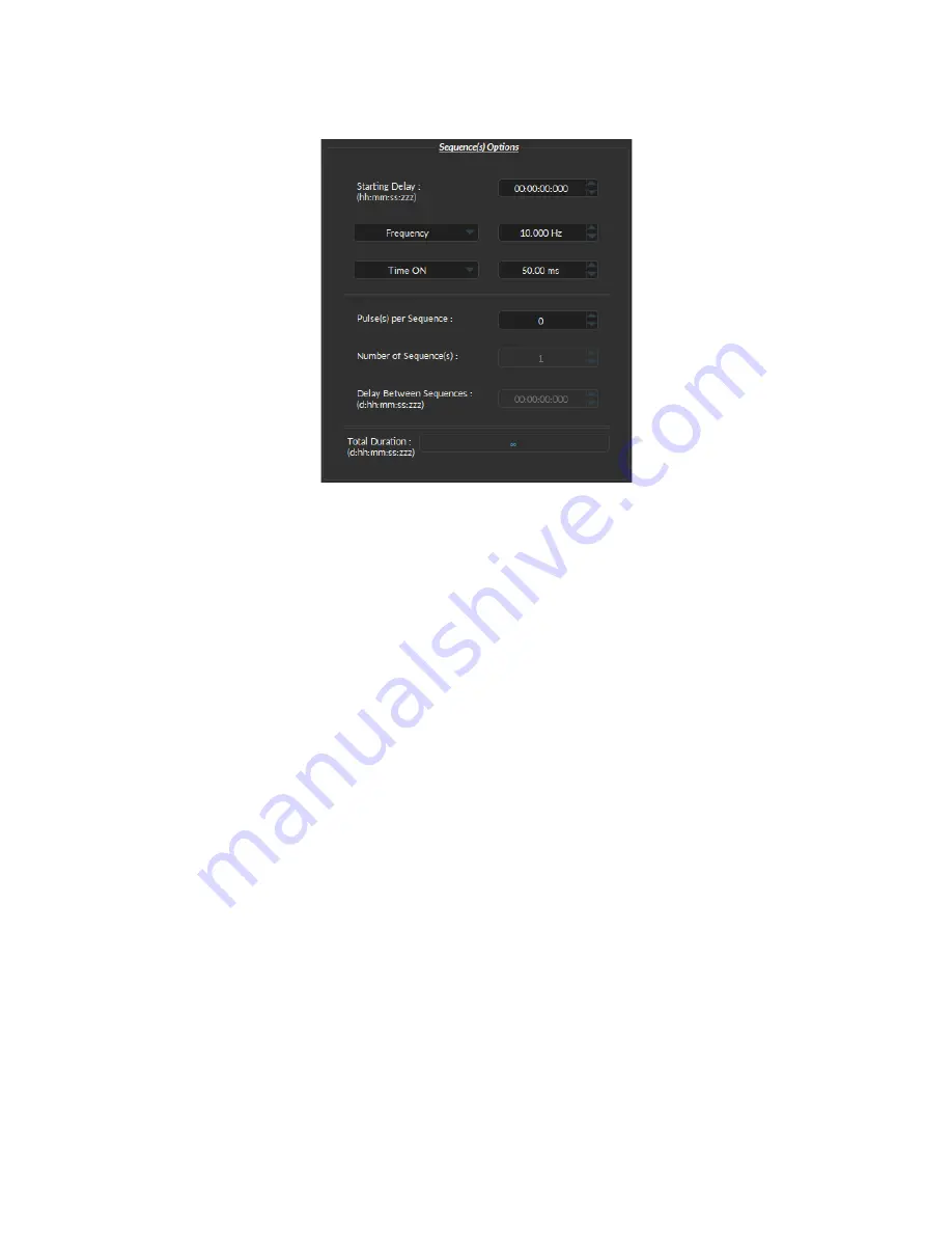
Figure 2.10:
Sequence Options of the Square Channel Mode.
The
Square
channel mode allows the creation of a square TTL pulse sequence. The Sequence Options of this mode
are shown in Figure
and are explained below.
1. The
Starting Delay
defines the time between the activation of the pulse sequence and the beginning of the
signal.
2. The
Frequency
sets the frequency (in Hz), which is the number of pulses per second. The frequency can also be
changed to the
Period
. For example, a signal at 10 Hz (frequency) will output one pulse every 100 ms (period),
whereas a signal at 0.5 Hz (frequency) will output one pulse every 2 seconds (period).
3. The
Time ON
defines the length of a single pulse. This time can also be converted to a
Duty Cycle
, which
represents the % of the period the pulse duration corresponds to.
4. The
Pulse(s) per sequence
set the number of pulses per sequence. If it is set to 0, the number of pulses will be
infinite.
5. The
Number of sequence(s)
sets the number of times that the sequence will be repeated.
6. The
Delay between sequences
sets the delay between each sequence.
7. The
Total Duration
shows the total expected duration of the pulse sequence. Should the duration be infinite,
the box will display
∞
. If there is an error in parameter selection, this box will display
N/A
.
Input Mode
The
Input
mode (Fig
) records a signal as long as there is a high TTL signal on the chosen console channel.
The channel can then be used as a trigger source for all the other channels of the OTPG. No
Sequence Options
or
Sequence Previews
are available for this mode.
Chapter 2. Operations Guide
10


