background image

4. The

Triggering Source

field defines if the sampling will be triggered manually (by clicking Live or Record) or will

be triggered by one of the input channel.

5. The

Saving Options

button opens an external window that allows you to configure the saving path and filename

of the channels signal file.

6. The

Target File

field indicates the saving path and filename of the channels signal file.

2.2.2 Configuration Tab

1

2

3

4

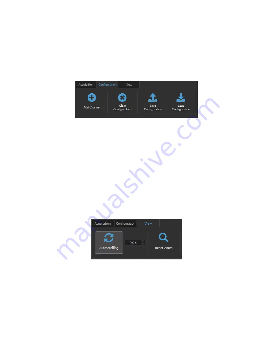
Figure 2.13:

Configuration Tab

The different buttons of the

Configuration Tab

are shown in Figure

2.13

and their functions are explained below.

1. The

Add Channel

button opens the

Channels configuration

window to setup the channels. This window is

detailed in section

2.1

.

2. The

Clear Configuration

button resets the acquisition view and all other parameters set. Any configurations

already set will be lost.

3. The

Save Configuration

button is used to save the OTPG configuration in a

.doric

format.

4. The

Load Configuration

button allows an OTPG configuration in

.doric

format to be loaded. Recorded data

files also contains the configuration used during the experiment and this configuration can be loaded using this

button.

2.2.3 View Tab

1

2

Figure 2.14:

View Tab

The different buttons and fields of the

View Tab

are shown in Figure

2.14

.

1. The

Autoscrolling

button, when clicked, makes the graphs scroll as new data appears. The duration (in seconds)

kept on display is controlled by the field beside the button.

2. The

Reset Zoom

button resets the horizontal axis of all graphs displayed in the

Acquisition View

to the duration

chosen in the

Autoscrolling

field.

Chapter 2. Operations Guide

12

Summary of Contents for OTPG 4

Page 1: ...Optogenetics TTL Pulse Generator User Manual Version 1 2 1...

Page 2: ...Overview 3 2 Operations Guide 4 2 1 Channel Con guration 5 2 2 Control and Settings 11 2 3 Acquisition View 13 3 Speci cations 14 4 Support 15 4 1 Maintenance 15 4 2 Warranty 15 4 3 Disposition 15 4...

Page 3: ...he most commonly used devices are LED Drivers Laser Drivers and Shutters It can be used to coordinate between many input output signal of di erent devices The generator comes in 4 channel Fig 1 1a and...

Page 4: ...nces can be designed for any type of experiment The OTPG user interface Fig 2 1 is split into two main sections the Controls Settings Section 2 2 and the Acqui sition view Section 2 3 From these secti...

Page 5: ...2 The Sequence Options de nes the parameters of each pulse sequence for the channel These parameters are di erent for each Channel Code Should a parameter chosen be impossible to apply to a sequence...

Page 6: ...t options of the Sequence Option section that are explained in more detail in section 2 1 3 3 The Inverted Output checkbox reverse the signal output When selected the ON TTL signal will send 0 V while...

Page 7: ...nd the sequence will continue when the next rising edge is received When the Repeatable sequence checkbox is checked the sequence will restart with the arrival of the rst input pulse after the sequenc...

Page 8: ...from the beginning when the next rising edge is received When the sequence is completed it will restart with the next input pulse Output Triggers a Triggered Non Repeatable Sequence Output Triggers b...

Page 9: ...The CW Continuous Wave channel mode allows the creation of a continuous TTL signal The following elements appear in the Sequence Options section Fig 2 9 1 The Starting Delay de nes the time between th...

Page 10: ...This time can also be converted to a Duty Cycle which represents the of the period the pulse duration corresponds to 4 The Pulse s per sequence set the number of pulses per sequence If it is set to 0...

Page 11: ...without recording their signal 2 The Record button starts all the con gured channels and record the signal for each of them at the de ned Sampling Frequency The recorded datas are saved in a doric le...

Page 12: ...Con guration button resets the acquisition view and all other parameters set Any con gurations already set will be lost 3 The Save Con guration button is used to save the OTPG con guration in a doric...

Page 13: ...iting of channel parameters opening the Channel Con guration window For additional information see section 2 1 3 The Graph s button opens an external window with options to change the displayed parame...

Page 14: ...bility 0 1 s Voltage Output 5 V Maximum Input Voltage 5 V TTL level Hi 3 3 V Low 1 5 V Current Consumption 100 mA 4 ch 200 mA 8ch Powered by computer USB port Output Current 20 mA Maximum Dimensions 4...

Page 15: ...ated in this manual For more information see our Website 4 3 Disposition Figure 4 1 WEEE directive logo According with the directive 2012 19 EU of the European Parliament and the Council of the Europe...

Page 16: ...2022 DORIC LENSES INC 357 rue Franquet Quebec Quebec G1P 4N7 Canada Phone 1 418 877 5600 Fax 1 418 877 1008 www doriclenses com...

Reviews: