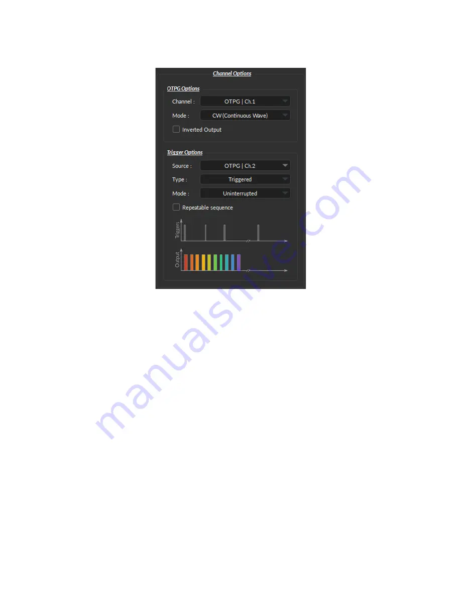
2.1.2 Channel Options Section
1
2
3
4
5
6
7
8
Figure 2.3:
Channel Options of the Channel Configuration Window.
The Channel Option section is separated in 2 sub-section, the
OTPG Options
section that defines the channel and its
mode and the
Trigger Options
section that control the trigger method of the selected channel. The Trigger Options
are not available when the channel is in Input mode.
OTPG Options
1. The
Channel
field identifies which of the available channels is currently being modified. The channel can be
changed by selecting a new one from the drop-down list.
2. The
Mode
field identifies the type of signal sent. Three modes are available,
CW (Continuous Wave)
,
Square
,
and
Input
mode. Each mode enables different options of the Sequence Option section that are explained in
more detail in section
3. The
Inverted Output
checkbox reverse the signal output. When selected, the ON TTL signal will send 0 V, while
the OFF TTL signal will send 5 V.
Trigger Options
4. The
Source
trigger option allows to chose between a
Manual Trigger
(activated by the user) or an
Input
trigger,
which is coming from a channel input.
5. The
Type
defines the type of trigger that is used to start/stop a sequence. The
Triggered
type can starts and
stops a sequence at a rising edge while the
Gated
type can starts the sequence at a rising edge and stops it at a
falling edge. A more refined interaction of the trigger with the defined sequence can be set up using the
Mode
field. Not all Trigger Type are available for each combination of Trigger Mode and Repeatability. The different
combinations are shown in Figure
Chapter 2. Operations Guide
6


