30
G60, G80, G100, G150, G200-SIIIA OM Manual
OPTIONS [CONT’D]
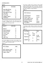
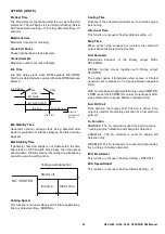
Figure 8
This screen displays the status of the binary inputs of the
controller. "I" indicates that an input has changed state
and "0" indicates no change of state.
Figure 9
This screen displays the status of the outputs of the
controller. "I" indicates that an output has changed state
and "0" indicates no change of state.
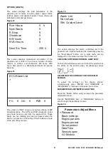
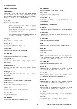
Figure 10
This screen is ONLY shown on Engines utilising J1939
engine communications. Indication of faults / shutdowns
from the engine control unit is shown here. The ECU
Yellow Lamp indicates an engine warning and the ECU
Red Lamp indicates an engine shutdown.
Figure 11
This screen is ONLY shown on engines utilising J1939
engine communications. The data is sent from the engine
ECU.
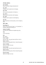
Figure 12
BIN
I000000
Rem Start/Stop
I
Low Coolant
0
Emergency Stop
0
Low Fuel
0
Full Basin
0
Voltage Select
0
VSS Door
0
BOUT
0000I00
Starter
0
Fuel Solenoid
0
Fuel Pull Coil
0
Glow Plugs
0
IL Power
I
Horn
0
GCB Trip
0
ECU State
000
ECU Yellow Lamp
0
ECU Red Lamp
0
Wait to Start
0
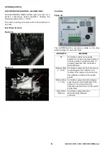
ECU Values
Oil Pressure
xxxxx
Water Temp
xxxxx
Perc Load ATCS
xxx
Boost Pressure
xxx
Manifold Temp
xxxxx
Fuel Rate
xxxxx
Act Power
0kW
0
0
0
Pwr factor
0.00
0.00
0.00
0.00
React pwr
0kVAr
0
0
0
Appar Pwr
0kVA
0
0
0
Summary of Contents for G06030001
Page 2: ......
Page 4: ...4 G60 G80 G100 G150 G200 SIIIA OM Manual ...
Page 8: ...8 G60 G80 G100 G150 G200 SIIIA OM Manual ...
Page 9: ...9 G60 G80 G100 G150 G200 SIIIA OM Manual ...
Page 10: ...10 G60 G80 G100 G150 G200 SIIIA OM Manual ...
Page 14: ...14 G60 G80 G100 G150 G200 SIIIA OM Manual ...
Page 89: ......
Page 90: ......


