background image

21

G60, G80, G100, G150, G200-SIIIA OM Manual

HAZARDOUS SUBSTANCE PRECAUTION

CAUTION

Use  extreme  care  to  avoid  contacting  hot  surfaces
(engine exhaust manifold and piping).

Ensure  that  adequate  ventilation  of  the  cooling  system
and exhaust gases is maintained at all times.

The following substances are used in the manufacture of
this  machine  and  may  be  hazardous  to  health  if  used
incorrectly.

Avoid ingestion, skin contact and breathing fumes for the
following substances: Antifreeze, Engine Lubricating Oil,
Preservative Grease, Rust Preventative, Diesel Fuel and
Battery Electrolyte.

The  following  substances  may  be  produced  during  the
operation  of  this  machine  and  may  be  hazardous  to
health:

Avoid  build-up  of  engine  exhaust  fumes  in  confined
spaces.

Avoid breathing exhaust fumes.

Avoid 

breathing 

brake 

lining 

dust 

during

maintenance.

Always operate in a well ventilated area.

GENERAL INFORMATION

Ensure  that  the  operator  reads  and  understands  the
decals and consults the manuals before maintenance or
operation.

Ensure  that  the  Operation  &  Maintenance  manual,  and
the  manual  holder,  are  not  removed  permanently  from
the machine.

Ensure  that  maintenance  personnel  are  adequately
trained,  competent  and  have  read  the  Maintenance
Manuals.

Make sure that all protective covers are in place and that
the canopy / doors are closed during operation.

The  specification  of  this  machine  is  such  that  the
machine  is  not  suitable  for  use  in  flammable  gas  risk
areas.  If  such  an  application  is  required  then  all  local
regulations,  codes  of  practice  and  site  rules  must  be
observed.  To  ensure  that  the  machine  can  operate  in  a
safe  and  reliable  manner,  additional  equipment  such  as
gas detection, exhaust spark arresters, and intake (shut-
off)  valves  may  be  required,  dependant  on  local
regulations or the degree of risk involved.

A  weekly  visual  check  must  be  made  on  all  fasteners  /
fixing  screws  securing  mechanical  parts.  In  particular,
safety-related  parts  such  as  coupling  hitch,  drawbar
components,  road-wheels,  and  lifting  bail  should  be
checked for total security.

All  components  which  are  loose,  damaged  or
unserviceable, must be rectified without delay.

Electricity

The human body has a low tolerance for electricity and is
a very good conductor. Exposure to electrical shock can
results in an interruption of normal heart activity, thermal
burns, severe muscle contractions and even death.

Never  operate  the  generator  without  all  protections  in
place. Controller and busbar doors must be closed at any
time during operation.

If life testing is necessary, it should only be performed by
properly trained people.

While  testing  on  life  electrical  equipment,  rubber  sole
shoes and adequate rubber gloves must be worn, and all
local regulations must be respected.

Materials

The  following  substances  may  be  produced  during  the
operation of this machine:

engine exhaust fumes

AVOID INHALATION.

Ensure  that  adequate  ventilation  of  the  cooling  system
and exhaust gases is maintained at all times.

WARNINGS

Warnings call attention to instructions which must be 
followed precisely to avoid injury or death.

CAUTIONS

Cautions call attention to instructions which must be 
followed precisely to avoid damaging the product, 
process or its surroundings.

NOTES

Notes are used for supplementary information.

Summary of Contents for G06030001

Page 1: ... who operate and maintain this machine 46606373_en_B_06 15 G60 G80 G100 G150 G200 SIIIA OPERATION MAINTENANCE MANUAL Original Instruction G60 SIIIA SERIAL No G06030001 G80 SIIIA SERIAL No G08030001 G100 SIIIA SERIAL No G10030001 G150 SIIIA SERIAL No G15030001 G200 SIIIA SERIAL No G20030001 ...

Page 2: ......

Page 3: ...NATOR INSTALLATION MAINTENANCE 69 REFERENCE INFORMATION Write the correct information for YOUR DIPP generator in the spaces below Always use these numbers when referring to your DIPP generator Doosan Benelux SA Drève Richelle 167 B 1410 Waterloo BELGIUM Generator Serial Number Engine Serial Number NOTES YOUR DIPP DEALER ADDRESS PHONE ...

Page 4: ...4 G60 G80 G100 G150 G200 SIIIA OM Manual ...

Page 5: ...5 G60 G80 G100 G150 G200 SIIIA OM Manual FOREWORD CONTENTS FOREWORD 6 DECLARATION OF CONFORMITY 7 ...

Page 6: ...ents to products sold previously The intended uses of this machine are outlined below and examples of unapproved usage are also given however the company cannot anticipate every application or work situation that may arise IF IN DOUBT CONSULT SUPERVISION This machine has been designed and supplied for use only in the following specified conditions and applications Operation within the ambient temp...

Page 7: ... level 21 Machine 23 Measured sound power level 24 Guaranteed sound power level CPN 46552201 rev E 1 EC Declaration of Conformity 2 3 We 4 Represented in EC by Doosan International USA Inc Doosan Trading Limited 1293 Glenway Drive Block B Swords Business Campus Statesville Swords North Carolina 28625 9218 Co Dublin USA Ireland 5 Hereby declare that under our sole responsibility the product s 6 Mac...

Page 8: ...8 G60 G80 G100 G150 G200 SIIIA OM Manual ...

Page 9: ...9 G60 G80 G100 G150 G200 SIIIA OM Manual ...

Page 10: ...10 G60 G80 G100 G150 G200 SIIIA OM Manual ...

Page 11: ...11 G60 G80 G100 G150 G200 SIIIA OM Manual GENERAL DATA CONTENTS GENERAL DATA 12 GENERAL INFO 12 ELECTRICAL DATA 13 ...

Page 12: ... level 97 dB A uncertainty 1 dB A The operating conditions of the machinery are in compliance with ISO 3744 1995 and EN ISO 8528 10 1998 UNIT MODEL G60 G80 G100 G150 G200 Engine Speed RPM 1500 1800 1500 1800 1500 1800 1500 1800 1500 1800 Engine Fuel Diesel Diesel Diesel Diesel Diesel Manufacturer John Deere John Deere John Deere John Deere John Deere Model 4045HFG81 4045HFG82 4045HFG82 6068HFG82 6...

Page 13: ... DATA UNIT MODEL G60 G80 G100 G150 G200 Nominal Apparent Power kVA Prime 60 80 100 150 200 Nominal Active Power kW Prime 48 64 80 120 160 Nominal Voltage 400 400 400 400 400 Nominal Current PF 1 69 93 116 173 231 Nominal Current PF 0 8 86 115 145 216 289 ...

Page 14: ...14 G60 G80 G100 G150 G200 SIIIA OM Manual ...

Page 15: ...Y CONTENTS SAFETY DECALS 16 GRAPHIC FORM AND MEANING OF ISO SYMBOLS 16 SAFETY INSTRUCTIONS 19 EARTHING 20 IF USED AS ALTERNATE POWER SUPPLY 20 HAZARDOUS SUBSTANCE PRECAUTION 21 GENERAL INFORMATION 21 Electricity Materials Battery Radiator Transport ...

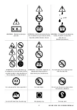
Page 16: ...WARNING Corrosion risk WARNING Air gas flow or Air discharge WARNING Pressurised vessel WARNING Hot and harmful exhaust gas WARNING Flammable liquid Do not stand on any service valve or other parts of the pressure system Do not operate with the doors or enclosure open Do not use fork lift truck from this side Do not remove the Operating and Maintenance manual and manual holder from this machine Do...

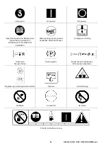
Page 17: ...anual WARNING Do not undertake any maintenance on this machine until the electrical supply is disconnected and the air pressure is totally relieved WARNING Consult the Operation Maintenance manual before commencing any maintenance Do not breathe the compressed air from this machine Do not exceed the trailer speed limit No naked lights Do not open the service valve before the airhose is attached Us...

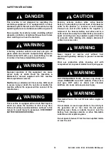
Page 18: ... maintenance of this machine is undertaken When parking use prop stand handbrake and wheel chocks Compressor oil filling Diesel fuel No open flame Parking brake Rough Service Designation Wet Location Operation Replace any cracked protective shield Oil drain Crush Warning No Water Coolant Fill No Flame Fill with fuel before start up ...

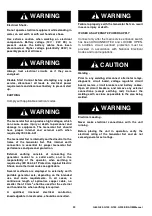
Page 19: ... recommendations outlined in this manual to avoid injury to personnel DISCONNECT BATTERY BEFORE SERVICING CAUTION Exercise extreme caution when using booster battery To jump battery connect ends of one booster cable to the positive terminal of each battery Connect one end of other cable to the negative terminal of the booster battery and other end to a earth connection away from dead battery to av...

Page 20: ...f the operator when earthing is required by IEC 364 4 41 Protection Against Electric Shock and other local codes as applicable Several methods are employed to externally earth portable generator sets depending on the intended use and code requirements In all cases a continuous length of splice free copper cable no smaller than 10 mm2 shall be used for the external earth conductor when earthing is ...

Page 21: ...nd site rules must be observed To ensure that the machine can operate in a safe and reliable manner additional equipment such as gas detection exhaust spark arresters and intake shut off valves may be required dependant on local regulations or the degree of risk involved A weekly visual check must be made on all fasteners fixing screws securing mechanical parts In particular safety related parts s...

Page 22: ...ne lubricants or fuel are inhaled Never give fluids or induce vomiting if the patient is unconscious or having convulsions Safety data sheets for engine lubricants and fuel should be obtained from the lubricant supplier Battery Batteries contain corrosive liquid and produce explosive gas Do not expose to naked lights Always wear personal protective clothing when handling When starting the machine ...

Page 23: ...AL CONTROLS OPERATION 28 Overview IDENTIFYING KEYPAD BUTTONS AND INDICATORS 28 Operation Buttons Display Buttons Status L E D S VIEWING REAL TIME DATA ACCESSING THE SCREENS 29 CHECKING SOFTWARE VERSION LAMP TEST 31 ADJUSTING THE CONTRAST ON THE DISPLAY SCREEN 31 PARAMETER ADJUSTMENTS VIA KEYPAD 31 SETPOINTS DESCRIPTIONS 32 Basic Settings Engine Parameters Engine Protection Alternator Protection Da...

Page 24: ...is positioned securely and on a stable foundation Any risk of movement should be removed by suitable means especially to avoid strain on any rigid discharge piping CONNECTING THE LOAD Make sure the wires are not cracked or damaged in any way Connect the proper phase wire to its corresponding bar L1 L2 L3 Mixing phases connections can result in equipment damage accidents causing injuries or even de...

Page 25: ...hould be glowing 9 With main breaker ON power is present and available for use 10 Close side doors for optimum cooling of the unit while running STOPPING 1 Turn off all external electrical power loads 2 Turn Main Breaker OFF 3 Allow 5 minute cool down 4 Push controller STOP Button 5 Wait at least 15 seconds before restarting 6 Fill fuel tank at end of working day to prevent condensate REMOTE START...

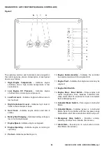
Page 26: ...low or not being charged 7 Engine Speed Indicates engine overspeed 8 Engine Operating Indicates engine is cranking or operating 9 Preheat Indicates preheating is on 10 Engine Communication Indicates the controller has communication with the engine ECU 11 Engine Fault Indicates that engine service may be required 12 Engine Start Switch 13 Engine Stop Reset Switch Stops engine and resets diagnostics...

Page 27: ...me for maintenance Monitor Switches 8 Amperage Output Selects the line phase amperage to be displayed on the AC Ammeter 9 Voltage Adjust Potentiometer Turn to adjust generator output voltage Protection Regulation 10 3 Phase Direct Hookup Connections L1 L2 L3 N neutral PE Protective Earth Not shown 11 Fuse Holders Fuses for voltage output meter Not shown 12 Residual Current Release Device RCD Provi...

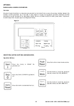
Page 28: ... also be viewed The parameters include but are not limited to kW KVA kVAr power factor oil pressure coolant temperature engine speed and diagnostic history Figure 4 IDENTIFYING KEYPAD BUTTONS AND INDICATORS Operation Buttons Press this button to START the generator set Press this button to STOP the generator set Press this button to deactivate the horn Press this button to clear inactive faults Us...

Page 29: ...onal screen which identifies the status of the generator set along with the generator kW power factor and engine RPM Figure 6 This screen displays electrical values of the generator set These values include frequency line voltages phase voltages and current per phase Figure 7 This screen displays the engine operational data of the generator set Use this button to scroll the display between the mea...

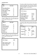
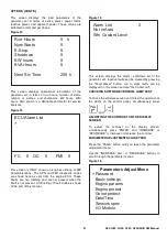
Page 30: ...n here The ECU Yellow Lamp indicates an engine warning and the ECU Red Lamp indicates an engine shutdown Figure 11 This screen is ONLY shown on engines utilising J1939 engine communications The data is sent from the engine ECU Figure 12 BIN I000000 Rem Start Stop I Low Coolant 0 Emergency Stop 0 Low Fuel 0 Full Basin 0 Voltage Select 0 VSS Door 0 BOUT 0000I00 Starter 0 Fuel Solenoid 0 Fuel Pull Co...

Page 31: ... the alarm shutdown list of the generator set Inactive faults can be cleared by pressing the Fault Reset button Up to eight faults can be displayed on this screen and are first in first out CHECKING SOFTWARE VERSION LAMP TEST To check the software version and to test the operation of the LEDs on the control panel simultaneously press and ADJUSTING THE CONTRAST ON THE DISPLAY SCREEN To adjust the c...

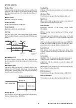
Page 32: ...age in LOW WYE Parallel connection Nominal Voltage 2 Line to neutral voltage in HI WYE series connection Gear Teeth Number of teeth on the engine gear for the pick up Set to zero if no pick up is used Engine speed is counted from the generator frequency Electronic engines get the speed signal from the engine controller Alternator Frequency Frequency of the battery alternator when the controller st...

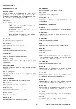
Page 33: ...r Cool Time This function is not used Factory default setting 0 Stop Time When genset stop sequence is initiated fuel solenoid output cannot activate during this time Fuel Solenoid Determines behavior of the Binary output FUEL SOLENOID DIESEL Output closes together with Binary output STARTER The output opens if Emergency stop comes or Cooled generator set is stopped or in pause between repeated st...

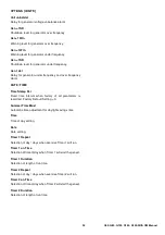
Page 34: ...l Level Del Delay for low fuel level Batt Overvolt Warning threshold for high battery voltage Batt Undervolt Warning threshold for low battery voltage Battvolt del Delay for low battery voltage alarm NextServTime h Counts down when engine running If reaches zero an alarm appears ALTERNATOR PROTECTION Overload Threshold for generator overload in of nominal power Overload Wrn Threshold for generator...

Page 35: ... TIME Time Stamp Per Fixed time interval when history of all parameters is recorded Factory Default Setting 0 Summer Time Mod Automatic time adjustment for daylight savings time Time Time of day setting Date Date setting Timer 1 Repeat Selection of day days when exercise Timer 1 will run Timer 1 on Time Selection of time of day when Timer 1 will start the genset Timer 1 Duration Selection of lengt...

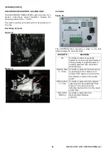
Page 36: ... state LED STATE MEANING Off Controller is either not currently powered or is being reverse powered Check polarity of supplied power If correctly powered then controller is malfunctioning Blinking Slow 1 2 Hz Controller is powered but not sensing a speed signal OK if engine is not running If the engine is running then this indicates a fault with the speed signal Blinking Fast 1 Hz Controller is po...

Page 37: ...us speed regulation keeping the frequency stable within 0 25 This option is factory set and should not be custom set in any way The dual freqency allows to easily switch from 50Hz to 60 Hz by toggling the frequency switch in the power pedestal No further action is required to change frequency Fuel Pump Actuator Figure 21 Figure 22 Controller Figure 23 Dual Frequency Switch Figure 24 ...

Page 38: ...s 3 8 BSPP Figure 25 3 way fuel valve Move the lever to the external fuel tank position Figure 26 Valve lever position Clean up any spilled fuel Connecting to external fuel connection preparation Stop the engine Connect the external fuel supply and return hoses to the external fuel connection Thread is 1 2 BSPP Figure 27 3 way fuel valve external connections Move the lever to the external fuel tan...

Page 39: ...ain valve Drain the engine oil using the hand pump Figure 30 Hand pump Recycle or dispose of used oil in an environmentally safe manner Close the engine oil pan drain valve WARNING AVOID INJURY OR DEATH Always clean up spilled fuel or oil Keep heat flames sparks or lighted tobacco away from fuel and oil Failure to use care around combustibles can cause explosion or fire SOCKET SET CE Figure 31 Soc...

Page 40: ...ed into land surfaces or drains Do not dispose of a complete machine without documentation relating to instructions for its use LONG TERM STORAGE RECOMMENDATIONS 6 MONTHS OR MORE Engine cooling system Treat with rust inhibitor and drain Check with engine dealer for further recommendations Seal all opening with waterproof tape Place a desiccant in the exhaust pipes and engine air intake pipes Loose...

Page 41: ...HOURS 49 CHANGE ENGINE OIL AND FILTER 49 CHANGE FUEL FILTER ELEMENTS 50 CHECK ENGINE MOUNTS 51 Check Engine Electrical Ground Connections CHECK BELT Engines with Manual Tensioner 51 CHECK BELT Engines with Automatic Tensioner 52 Check Belt Wear Check Tensioner Spring Tension CHECK COOLING SYSTEM 53 Test Radiator Cap Test Cooling System CHECK AIR INTAKE SYSTEM 54 MAINTENANCE 2000 HOURS 2 YEARS 55 C...

Page 42: ...0 G100 G150 G200 SIIIA OM Manual REPLACE FAN ALTERNATOR POLY V BELT 60 BLEED THE FUEL SYSTEM 61 4045 Engines with Mechanical Fuel System Engines with HPCR Fuel System ENGINE TROUBLESHOOTING 63 SPECIFICATIONS 67 ...

Page 43: ...he earthing terminal frame generator and engine block Hoses Each month it is recommended that the intake hoses from the air cleaner and all flexible hoses used for water and fuel be inspected for the following 1 All rubber hose joints and the screw type hose clamps must be tight and the hoses showing no signs of wear abrasion or deterioration 2 All flexible hoses must be free of wear deterioration...

Page 44: ...s are for normal operating conditions Service MORE OFTEN if engine is operated under adverse conditions Neglecting maintenance can result in failures or permanent damage to the engine Use correct fuels lubricants and coolant CAUTION Use only fuels lubricants and coolants meeting specification outlined in Fuels Lubricants and Coolant Section when servicing your John Deere Engine Consult your John D...

Page 45: ...ozzles every 5000 hours and thermostat every 10000 hours Item 10 H Daily Every 2 Weeks 500 H 1000 H 1 Year 2000H 2 Years 3000 H 3 Years 4500 H As Required Check engine oil and coolant level Check air filter restriction indicator a Check fuel filter water bowl Operate engine at rated speed and 50 70 load a minimum of 30 minutes b Change engine oil and filter c Replace fuel filter element s Check cr...

Page 46: ...e crosshatch area Oil levels anywhere within crosshatch area are considered in the acceptable operating range CHECK COOLANT LEVEL WARNING Explosive release of fluid from pressurized cooling system can cause serious burns Only remove filler cap when engine is cold or when cool enough to touch with bare hands Slowly loosen cap first to relieve pressure before removing completely Figure 34 Radiator C...

Page 47: ...all fittings caps and plugs before performing any maintenance to reduce the chance of system contamination CHECK FUEL FILTER NOTE Engines have two fuel filters primary and final equipped with a water in fuel sensor Depending on application an indicator light on the instrument panel will signal the operator that water should be drained from filter bowls Figure 37 Drain Water from Fuel Filters Check...

Page 48: ...oximately 5 minutes to warm up oil Shut engine off 2 Open oil pan drain valve A 3 Drain crankcase oil from engine while warm 4 Replace oil filter as follows a Remove and discard oil filter element B using a suitable filter wrench b Apply clean engine oil to inner C and outer D seals and to filter threads c Wipe both sealing surfaces E of the filter header Oil Filter Header with a clean rag Ensure ...

Page 49: ...ngine B To determine the correct oil fill quantity for your engine see the Specification Section NOTE Crankcase oil capacity may vary slightly ALWAYS fill crankcase to full mark or within crosshatch area on dipstick A whichever is present DO NOT overfill Figure 44 Crosshatch Area on Oil Dipstick 7 Start engine and run to check for possible leaks 8 Stop engine and check oil level after 10 minutes I...

Page 50: ...rotated helps to get it past raised locators 4 Firmly grasp the retaining ring A and rotate it clockwise 1 3 turn Remove ring along with filter element B or F CAUTION Do not dump the old fuel into the new filter element This could cause fuel injection problems A plug is provided with the new element for plugging the used element 5 Inspect filter mounting base for cleanliness Clean as required NOTE...

Page 51: ... crushed due to a loss of elasticity Check Engine Electrical Ground Connections Keep all engine ground connections clean and tight to prevent electrical arcing which can damage engine or electronic components CHECK BELT Engines with Manual Tensioner Figure 47 Manual Belt Tensioner Figure 48 Reference Marks Inspect belts for cracks fraying or stretched out areas Replace if necessary NOTE Belt adjus...

Page 52: ...swing arm A is hitting the fixed stop B check mounting brackets alternator belt tensioner idler pulley etc and the belt length Replace belt as needed see Replace Fan and Alternator Belt Maintenance As Required Section Check tensioner spring tension Figure 50 Marks on Tensioner Figure 51 Align Marks A belt tension gauge will not give an accurate measure of the belt tension when automatic spring ten...

Page 53: ...TE Engine should be warmed up to test overall cooling system Figure 53 Test Radiator Cap 1 Allow engines to cool then carefully remove radiator cap 2 Fill radiator with coolant to the normal operating level CAUTION DO NOT apply excessive pressure to cooling system doing so may damage radiator and hoses 3 Connect gauge and adapter to radiator filler neck Pressurize cooling system to specification l...

Page 54: ...ng for cracks Replace as necessary 2 Check clamps on air pipes A which connect the air filter engine and if present turbocharger and air to air radiator Tighten clamps as necessary 3 Test air restriction indicator B for proper operation Replace indicator as necessary 4 If engine has a rubber dust unloader valve C inspect the valve on bottom of air filter for cracks of plugging Replace as necessary...

Page 55: ...djusting screw Turn adjusting screw until feeler gauge slips with a slight drag Hold the adjusting screw from turning with screwdriver and tighten locknut A to 27N m 20lb ft Recheck clearance after tightening locknut Readjust clearance as necessary 5 Reinstall rocker arm cover and crankcase vent tube 4045 Engine NOTE Firing order is 1 3 4 2 Figure 57 Valve Clearance Adjustment on 4045 Engines 1 Lo...

Page 56: ...mpression stroke B 2 Adjust valve clearance on No 1 3 and 5 exhaust valves and No 1 2 and 4 intake valves 3 Rotate flywheel 360 Lock No 6 piston at TDC compression stroke C 4 Adjust valve clearance on No 2 4 and 6 exhaust valves and No 3 5 and 6 intake valves A Front of Engine B No 1 Piston at TDC Compression Stroke C No 6 Piston at TDC Compression Stroke E Exhaust Valve I Intake Valve Compression...

Page 57: ...st or sediment 6 Stop engine and immediately drain the water from system before rust and sediment settle 7 After draining water close all drain orifices and fill the cooling system with cleaning product such as PMCC2610 or PMCC2638 Cooling System Cleaners available from your John Deere Dealer Follow manufacturer s directions on label 8 After cleaning the cooling system drain cleaner and fill with ...

Page 58: ...he proper dust cap or an appropriate seal to protect it from foreign debris and moisture 3 Control units are not repairable 4 Since control units are the components LEAST likely to fail isolate failure before replacing by completing a diagnostic procedure See your John Deere dealer 5 The wiring harness terminals and connectors for electronic control units are repairable CLEAN OR REPLACE AIR FILTER...

Page 59: ...r filter area 2 Unlatch and remove air filter cover A 3 Remove air filter element B from canister 4 Clean all dirt from inside canister CAUTION Do not reinstall an air filter element which shows evidence of bad condition punched dented etc allowing no filtered air to enter the engine 5 Clean air filter element with compressed air working from clean to dirty side NOTE Compressed air pressure must n...

Page 60: ...ermine if belt needs to be replaced 1 Inspect belts for cracks fraying or stretched out areas Replace if necessary 2 On engines with automatic belt tensioner release tension on belt using a breaker bar and socket on tension arm On engines with manual tensioner loosen cap screws holding the alternator 3 Remove poly V belt from pulleys and discard belt 4 Install new belt making sure belt is correctl...

Page 61: ...Whenever the fuel system has been opened up for service lines disconnected or filters removed it will be necessary to bleed air from the system On dual fuel filter system bleed air only from final filter 4045 Engines with Mechanical Fuel System Figure 66 Fuel Filter Bleed Screw 1 Loosen the air bleed screw A two full turns 2 Operate fuel pump primer lever B until fuel flow is free from air bubbles...

Page 62: ...cing dealer or engine distributor Bleed Fuel System at Fuel Injection Nozzles Engines with HPCR Fuel System WARNING High pressure fluid remaining in fuel lines can cause serious injury Do not disconnect fuel lines between the high pressure fuel pump and nozzles Only bleed the fuel system at the fuel filter bleed screw A Figure 70 Final Fuel Filter Bleed Screw Figure 71 Fuel Pump Primer Lever 1 Loo...

Page 63: ...Use cold weather starting aids Slow starter speed See Starter Cranks Slowly Crankcase oil too heavy Use oil of proper viscosity Improper type of fuel Consult fuel supplier use proper type fuel for operating conditions Water dirt or air in fuel system Drain flush fill and bleed system Clogged fuel filter Replace filter element Dirty or faulty injection nozzles Have authorized servicing dealer or en...

Page 64: ...cing dealer or engine distributor Low oil level Add oil Improper type of oil Drain fill crankcase with oil of proper viscosity and quality High oil consumption Crankcase oil too light Use proper viscosity oil Oil leaks Check for leaks in lines gaskets and drain plug Restricted crankcase vent tube Clean vent tube Defective turbocharger See your authorized servicing dealer or engine distributor Engi...

Page 65: ... distributor Defective turbocharger See your authorized servicing dealer or engine distributor Low engine temperature Check thermostat Undercharged system Excessive electrical load from added accessories Remove accessories or install higher output alternator Excessive engine idling Increase engine rpm when heavy electrical load is used Poor electrical connections on battery ground strap starter or...

Page 66: ... engine distributor Crankcase oil too heavy Use proper viscosity oil Loose or corroded connections Clean and tighten connections Entire electrical system Faulty battery connection Clean and tighten connections Sulfated or worn out batteries See your authorized servicing dealer or engine distributor Blown fuse Replace fuse ...

Page 67: ...305 225 3 4 120 88 150 110 190 140 240 175 300 220 380 280 425 315 540 400 7 8 190 140 240 175 190 140 240 175 490 360 615 455 690 510 870 640 1 285 210 360 265 285 210 360 265 730 540 920 680 1030 760 1300 960 1 1 8 400 300 510 375 400 300 510 375 910 670 1150 850 1450 1075 1850 1350 1 1 4 570 420 725 535 570 420 725 535 1280 945 1630 1200 2050 1500 2600 1920 1 3 8 750 550 950 700 750 550 950 700...

Page 68: ...0 480 725 535 920 680 850 625 1080 800 M24 330 245 425 315 650 480 820 600 920 680 1150 850 1080 800 1350 1000 M27 490 360 625 460 950 700 1200 885 1350 1000 1700 1250 1580 1160 2000 1475 M30 660 490 850 625 1290 950 1630 1200 1850 1350 2300 1700 2140 1580 2700 2000 M33 900 665 1150 850 1750 1300 2200 1625 2500 1850 3150 2325 2900 2150 3700 2730 M36 1150 850 1450 1075 2250 1650 2850 2100 3200 2350...

Page 69: ...ECTRICAL CHARACTERISTICS 72 MECHANICAL OPTIONS 72 INSTALLATION 73 ASSEMBLY 73 Handling Coupling Location CHECKS PRIOR TO FIRST USE 73 Electrical checks Mechanical checks TERMINAL CONNECTION DIAGRAMS 74 Terminal connection 12 wire Terminal connection 6 wire not possible with the R 250 Connection checks COMMISSIONING 76 SETTING UP 77 SERVICING MAINTENANCE 77 SAFETY MEASURES 77 ROUTINE MAINTENANCE 77...

Page 70: ...ing separate excitation DISMANTLING REASSEMBLY 81 Tools required Screw tightening torque Access to diodes Access to connections and the regulation system Replacing the NDE bearing Dismantling the rotor assembly Reassembling the machine Dismantling and reassembly of the filters TABLE OF CHARACTERISTICS 84 EXPLODED VIEW PARTS LIST AND TIGHTENING TORQUE 86 ...

Page 71: ...ing symbols used CAUTION Warning symbol for an operation capable of damaging or destroying the machine or surrounding equipment WARNING Warning symbol for general danger to personnel Warning symbol for electrical danger to personnel WARNING SYMBOLS We wish to draw your attention to the following 2 safety measures which must be complied with a During operation do not allow anyone to stand in front ...

Page 72: ... STORAGE Prior to commissioning machines should be stored Away from humidity 90 after a long period of storage check the machine insulation See Electrical checks on page 73 To prevent the bearings from becoming marked do not store in an environment with significant vibration APPLICATION These alternators are mainly designed to produce electricity in the context of applications involving the use of...

Page 73: ...ing discs should be aligned with the flywheel holes by cranking the engine Make sure the alternator is securely bedded in position during coupling Check that there is lateral play on the crankshaft Double bearing alternator Semi flexible coupling Careful alignment of the machines is recommended checking that the lack of concentricity and parallelism of both parts of the coupling do not exceed 0 1 ...

Page 74: ...nal connection 12 wire Any intervention on the alternator terminals during connection or checks should be performed with the machine stopped Connection codes Voltage L L Factory connection L1 U N L3 W T1 T7 T12 T10 T4 T9 T3 T6 T11 T5 T2 T8 L2 V A 3 phase 3 phase Winding 60 Hz 50 Hz 190 208 190 240 220 190 208 6 7 8 6 7 8 9 N T1 T7 T12 T10 T4 T9 T3 T6 T11 T5 T2 T8 L1 U L3 W L2 V D R 250 voltage det...

Page 75: ... T4 T12 T6 T10 T5 T7 T8 T9 6 7 8 6 7 8 F L1 U M L3 W T1 T7 T12 T10 T4 T9 T3 T6 T11 T5 T2 T8 L2 V L1 U L2 V L1 U L2 V L3 W 1 phase 1 phase or 3 phase FF G Winding 60 Hz 50 Hz 220 240 220 240 220 240 240 254 R 250 voltage detection 0 T4 110 V T1 R 450 voltage detection 0 T10 220 V T1 R 250 voltage detection 0 T8 110 V T11 R 450 voltage detection 0 T3 220 V T2 NDE Winding 6 7 8 Winding 60 Hz 50 Hz 22...

Page 76: ...e circuit not protected by circuit breakers or relays in the cabinet The machine should be connected with the busbar separating the terminals as shown in the terminal connection diagram COMMISSIONING WARNING The machine can only be started up and used if the installation is in accordance with the regulations and instructions defined in this manual Connection codes Voltage L L Factory connection 3 ...

Page 77: ... on the machine ensure that it cannot be started by a manual or automatic system and that you have understood the operating principles of the system ROUTINE MAINTENANCE Checks after start up After approximately 20 hours of operation check that all fixing screws on the machine are still tight plus the general state of the machine and the various electrical connections in the installation Bearings A...

Page 78: ...fitted with air inlet and outlet filters the maintenance personnel should clean them routinely at regular intervals In the case of dry dust the filter can be cleaned using compressed air and or replaced if it is clogged After cleaning the alternator it is essential to check the winding insulation See CHECKS PRIOR TO FIRST USE on page 73 FAULT DETECTION If when commissioned the alternator does not ...

Page 79: ... partially clogged or hot air is being recycled from the alternator or engine Alternator operating at too high a voltage 105 of Un on load Alternator overloaded Vibration Excessive vibration Misalignment coupling Defective mounting or play in coupling Rotor balancing fault Engine Alternator Excessive vibration and humming noise coming from the machine Phase imbalance Stator short circuit Abnormal ...

Page 80: ...y be faulty Field windings short circuited Rotating diodes burnt out Revolving field coil short circuited Check the resistance Speed too low Increase the drive speed do not touch the AVR voltage pot P2 before running at the correct speed Voltage too high Adjust AVR voltage potentiometer Adjustment ineffective Faulty AVR Voltage oscillations Adjust the AVR stability potentiometer If no effect try n...

Page 81: ...the exciter field current by adjusting the rheostat or the variac and measure the output voltages on L1 L2 L3 checking the excitation voltage and current at no load see the machine nameplate or ask for the factory test report When the output voltage is at its rated value and balanced within 1 for the rated excitation level the machine is in good working order The fault therefore comes from the AVR...

Page 82: ...ield 36 Take out the anti friction bearing 70 using a puller with a central screw see drawing below Fit the new anti friction bearing onto the shaft after heating it by induction to approximately 80 C Mount the new pre loading wavy washer 79 the new O ring seal 349 in the shield 36 and coat the bearing seat with adhesive paste see After Sales Service If using a single bearing or double bearing mac...

Page 83: ...ble bearing option Mount the new pre loading wavy washer 79 the new O ring seal 349 in the shield 36 Screw a threaded rod into the thrust bearing 78 Refit the shield 36 on the machine using a dowel and nut in the shaft extension see diagram Slide the threaded rod into the shield hole to make it easier to assemble see diagram Fit the thrust bearing screws 78 remove the threaded rod fit the other sc...

Page 84: ...IIA Three phase 4 pole AREP excitation Resistances at 20 C Ω Resistance of auxiliary windings at 20 C Ω Field excitation current i exc A 400V 50 Hz i exc excitation current of the exciter field Table of weights values given for information only 42 3 Stator L N Rotor Field coil Armature L9 0 095 0 91 7 35 0 20 Type X1 X2 auxil wdgs Z1 Z2 auxil wdgs L9 0 313 0 433 Type No load At rated load L9 0 87 ...

Page 85: ...eld Table of weights values given for information only The voltage and current values are given for no load operation and operation at rated load with separate field excitation All values are given to be within 10 All values are given at 50 Hz 44 2 Stator L N Rotor Field coil Armature M5 0 0182 0 24 8 8 0 035 Type X1 X2 auxil wdgs Z1 Z2 auxil wdgs M5 0 216 0 363 LSA 44 2 No load At load M5 1 1 3 8...

Page 86: ... box lid 49 Terminal box screw M5 3 6 0 4 53 1 Plug 59 1 Access flap M5 3 6 0 4 70 1 NDE bearing 79 1 Preloading wavy washer 90 1 Wound exciter field 91 4 Field fixing screw M6 10 100 1 Exciter armature 120 1 Terminal plate support M5 6 124 1 Terminal plate M5 6 198 1 Regulator AVR M5 4 0 5 199 Interference suppression module M5 6 343 2 Direct diode assembly M5 4 349 1 0 ring seal 1 AVR fuses ...

Page 87: ...t panel 47 1 Cover rear panel 48 1 Cover top panel 49 34 Fixing screws M6 5 59 3 Inspection door 70 1 NDE bearing 79 1 Preloading wavy washer 90 1 Wound exciter field 91 4 Field fixing screw M6 10 100 1 Exciter armature 120 1 Terminal block support 124 1 Terminal block M10 20 198 1 Voltage regulator AVR 343 1 Diode bridge assembly M6 5 349 1 O ring ...

Page 88: ... G200 SIIIA REF QTY DESCRIPTION SCREW Ø TORQUE N M 70 1 Non drive end bearing 79 1 Preloading wavy washer 90 1 Exciter field 100 1 Exciter armature 124 1 Terminal plate M12 35 198 1 Voltage regulator AVR 343 1 Diode bridge assembly M6 4 347 1 Protection varistor PCB ...

Page 89: ......

Page 90: ......

Reviews: