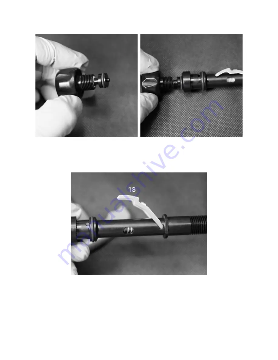
10. Take the assembled Adjust Knob - Fig. 36 and insert it into the Adjust Tube and begin to screw it in
- Fig. 37.
Fig. 36 Fig. 37
11. Screw the Adjust Knob assembly into the tube until you can see clearly through the hole for the Pin
(19). As the assembly is turned in, the Lever will rise - Fig. 38. If it does not, it may have become
disengaged during the installation of the Lever. Remove and reinstall it as referenced in Step 8.
Fig. 38
Summary of Contents for DGX Gears D6
Page 1: ...DGX Gears D6 Second Stage Service Manual...
Page 32: ......


