2 / 20
Any type of modification to any Distech Controls product will void the product’s warranty
Take special care to keep the front and back plate aligned when separating and joining them.
Before installation of the Wireless Receiver, verify that local communication regulations allow the installation of wireless devices and
available frequencies to be supported in your area. Refer to the Open-to-Wireless™ Application Guide for more information.
Take reasonable precautions to prevent electrostatic discharge to the device when installing, servicing or during operation. Discharge
accumulated static electricity by touching one’s hand to a well-grounded object before working with the device.
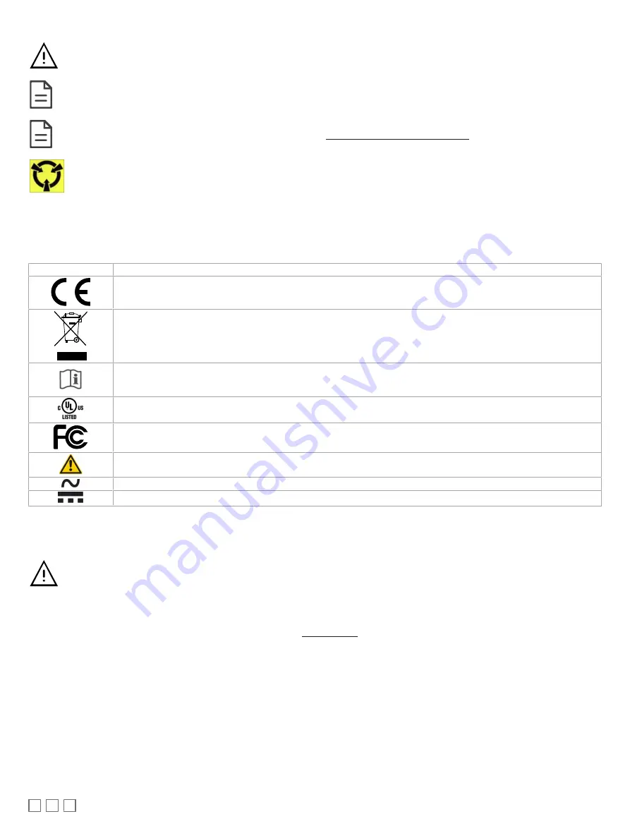
Device Markings (Symbols)
Certain markings (symbols) can be found on the controller and are defined as follows:
Symbol
Description
CE marking: the device conforms to the requirements of applicable EC directives.
Products must be disposed of at the end of their useful life according to local regulations.
Read the Hardware Installation Guide for more information.
UL marking: conforms to the requirements of the UL certification.
FCC marking: This device complies with FCC rules part 15, subpart B, class B.
Warning Symbol: Significant information required. Refer to the Hardware Installation Guide.
Alternating Current
Direct Current
General Wiring Recommendations
Risk of Electric Shock: Turn off power before any kind of servicing to avoid electric shock.
£
All wiring must comply with electrical wiring diagrams as well as national and local electrical codes.
£
To connect the wiring to a device, use the terminal connectors. Use a small flat screwdriver to tighten the terminal connector screws once the wires
have been inserted (strip length: 0.25’’ (6 mm), maximum tightening torque 0.5 Nm).
£
Comply with all network and power supply guidelines outlined in the Network Guide.
£
Always use unshielded cabling with a minimum Category 5 (CAT5) cable for ethernet communications.
£
Keep wiring separate according to their function and purpose to avoid any ambient noise transmission to other wires. Use strapping to keep these
wires separated. For example, keep power, hazardous voltage, SELV, PELV, network, and input wiring separate from each other.
£
The board connectors accept wires or flat cables ranging from 22 to 14AWG (0.644 to 1.630mm diameter) per pole. However, power cables must be
between 18 and 14AWG (1.024 to 1.630mm diameter).
£
Keep all wires away from high speed data transmission cables (for example, Ethernet, etc.).
£
Do not connect the universal inputs, analog/digital outputs or common terminals to earth or chassis ground (unless stated otherwise).
£
Keep input and output wiring in conduits, trays or close to the building frame if possible.


