


【
4-3
】
SUSPENSION/STEERING
Suspension Arms
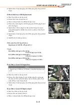
Suspension Arm Removal
●
Remove:
Front Wheel (see Wheels/Tires chapter)
Front Hub (see Wheels/Tires chapter)
Cotter Pin, Nut and Bolt [A]
Tie-Rod End [B]
Front Shock Absorber Mounting Bolts [C]
Suspension Arm Pivot Bolts [D]
Suspension Arm Installation
●
Tighten:
Torque –
Suspension Arm Pivot Bolts: 88 N-m (9.0 kgf-m, 65 ft-lb)
Steering Knuckle Joint Nut: 42 N-m (4.3 kgf-m, 31 ft-lb)
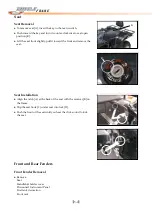
Suspension Arm Disassembly
●
Remove:
Bolts
Caps
Bushings
Spacer
●
Holding the suspension arm with a vise, remove the cotter pin[A]
and unscrew the castle nut [B], and then remove the knuckle joint
and circlip.
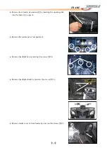
Suspension Arm Assembly
●
When installing the rubber bushing into the arm, lubricate the
outer surface of the bushings with a soap and water solution.
●
Position the bushings in the suspension arm as shown using a
suitable bearing driver in the bearing driver set.
A
B
C
A
CAUTION
Do not remove the knuckle joint grease seal. It is packed with
grease.
CAUTION
Do not lubricate the rubber bushings with engine oil or
petroleum distillates because they will deteriorate the rubbers.
Summary of Contents for DL702
Page 1: ... 0 0 FOREWORD INDEX ...
Page 88: ... 7 13 ELECTRICAL SYSTEM Wiring Diagram ...
Page 89: ... 7 14 ELECTRICAL SYSTEM Wiring Diagram ...
Page 90: ... 7 15 ELECTRICAL SYSTEM NOTE ...


