EN-6
451903.66.17 · FD 9908
www.gdts.one
English
LWP 200E
4 Installation
4.1 Installation location
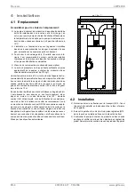
Installation location criteria:
The domestic hot water heat pump must be installed in a
dry, frost-free room; to ensure effective heat pump opera-
tion, the temperature of the air drawn in by the domestic hot
water heat pump should also not fall below 15 °C.
Furthermore, installation and air intake is not permitted in
rooms with air which is potentially explosive because of
gases, vapours or dust.
In order to prevent damage to interior walls caused by
dampness, it is recommended to provide good thermal insu-
lation between the room into which the exhaust air is re-
leased and the neighbouring rooms.
Condensate drainage (with a siphon) must be provided.
The load-bearing capacity of the foundation must be suffi-
cient (the weight of the filled domestic hot water heat pump
is approx. 270 kg).
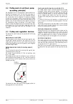
We recommend a minimum clearance of 0.5 m to allow for main-
tenance and repair work on all sides of the device. The domestic
hot water heat pump can optionally be connected using insulated
NW 125 air ducts, which must not exceed a total length of 10 m.
To ensure effective operation, an air circuit bend (90° NW 125)
must be installed on the blow-out side in rooms with lower ceil-
ings and without ductwork. If the air circuit bend is used, place it
onto the spigot (or in the sleeve with a nominal width of DN 125
required for assembly) of the outlet side so that the outlet open-
ing of the air circuit bend is as far away from the unit's air intake
opening as possible. The air connection stubs of the domestic
hot water heat pump “intake stub” and “outlet stub” are labelled.
4.2 Installation
Remove the three transport restraint screws (M12 - fixing
the device to the pallet) from the bottom of the pallet.
Remove the pallet and mount the three M12 supporting feet
(in the plastic bag attached to the nipple of the cylinder pipe).
Position the domestic hot water heat pump and align it verti-
cally by adjusting the device feet. Then tighten the counter-
nuts on the device feet.
ca. 1,5 m **
c
a
.
2
,0
m
*


