78
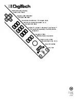
BLOCK DIAGRAM
Following is a simplified block diagram of the Valve FX.
S-DISC™
Processor
(DSP)
Compressor
Distortion
Presence
Front Panel Input
Rear Panel Input
A / D
Converter
D/A
Converter
1/4" Output Right
1/4" Output Left
Headphone Output
Output
Level
Meter
Bypass
Switch
Section 6 - Appendix
Valve FX Owner’s Manual


