background image

59  | VMAX IP Plus™ NVR


-59- 


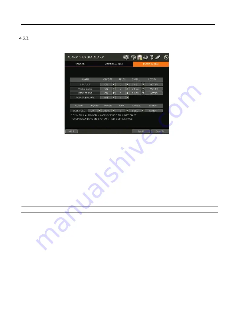
Extra Alarm 

Setup alarms for additional NVR abnormalities such as SMART HDD check, VIDEO LOSS, RECORDING 

FAILURE and DISK FULL. 


S.M.A.R.T.   

Trigger an alarm signal when HDD is about to be out of operation. Please refer to “4.1.4 HDD” to 

check the HDD status. 

VIDEO LOSS 

Trigger an alarm signal when a camera signal is disconnected. 

RECORDING FAILURE 

Trigger an alarm signal when the system does not record images due to an error in HDD or system. 

DISK FULL 

Trigger an alarm signal when the HDD is occupied with a certain percentage of its capacity. If the 

user sets HDD FULL as STOP RECORDING and the HDD is occupied with the certain percentage set 

here, NVR stops recording and the alarm trigger. 

Note 

The extra-alarm will appear in the event log only when it is set as “ON”. 


Summary of Contents for DW-VP1212T8P

Page 1: ...ing to the specification and model Contents of this user manual are protected under copyrights and computer program laws Rev 12 21 Before operating the system please read this User Manual and retain it for future reference USER MANUAL ...

Page 2: ...WARNING TO REDUCE FIRE OR SHOCK HAZARD DO NOT EXPOSE THE UNIT TO RAIN OR MOISTURE The installation should be made by a qualified service person and conformed to all local codes ...

Page 3: ...ir inhaler of the front panel and air outlet of the back panel must not be blocked during installation The internal temperature of the product would be greater than allowable and could cause malfunction or fire 4 Do not touch the product or the power cord when there is thunder It may cause an electric shock 5 Do not install the product near or on top of the heating source The internal temperature ...

Page 4: ...3 DELETING CAMERAS 21 3 4 CAMERA SETUP 22 3 5 LIVE DISPLAY MODE 24 3 6 PTZ OPERATION 28 3 7 PLAYBACK RECORDED IMAGES 29 3 8 SEARCH RECORDED IMAGE 31 3 10 SPECIAL CAMERA SEARCH 36 3 11 DST SETTING AND IMAGE PLAYBACK 37 3 12 MEGAPIX IVA ANALYTICS 38 4 SETTING 42 4 1 SYSTEM 43 4 2 DEVICE 49 4 3 ALARM 56 4 4 RECORD 60 4 5 NETWORK 64 4 6 EXPORT 73 5 WEB SURVEILLANCE THROUGH INTERNET EXPLORER 76 5 1 WEB...

Page 5: ...ied with your NVR If any of these items are missing or damaged notify your vendor immediately Keep the packing utilities for moving or storage purposes afterward Items Photo Quantity Quick setup guide and download instruction card 1 9CH models 48V D C adaptor and power cable 12CH and 16CH models a power cable 1 USB mouse 1 ...

Page 6: ...nistrator Account configurable in the NVR It is assigned with an unchangeable User ID marked as admin The administrator account has full access to the NVR and its configurable parameters and can also create new users and assign rights to the new user accounts If NVR is set as AUTO LOGIN the login process is not necessary Caution 1 It may take a few minutes to start up the system after turning on t...

Page 7: ...t the password and click OK to shut down the system Click YES to confirm shutdown Note Users can input passwords by the virtual keyboard IR remote control or front numeric buttons if available 1 4 System Explanation Front Panel Front panel may differ according to the model 1 Power button On the back side 2 LED indicator indicates system status for power record and network status 3 USB port for bac...

Page 8: ...rding to the model The model shown in the diagram above is the 16CH DW VP16xT16P NVR The audio input port in the NVR is disabled by default For audio recording use an audio input supported IP camera Note On DW VP9xT4P models users must use the case s ground when connecting alarm inputs to the NVR ...

Page 9: ...ncy Recording Button 15 Auto Sequence Button in Live mode 16 Screen Mode Button 17 Backup Button Note Users can control multiple NVRs with one IR remote controller To control multiple NVRs each NVR must have a different remote ID The default remote ID is 0 To setup the ID in the IR remote controller 1 Press and hold the ID selection button for 5 seconds 2 Set the new ID by pressing the numeric but...

Page 10: ...ingle channel view of a specific channel by pressing the corresponding number Emergency Recording The system records all channels with the full frame rate at the maximum resolution regardless of the recording setting To stop the emergency recording click the same icon again Backup Backup recorded video to an external device See 0 Backup for details Playback Switch to playback mode See 3 7 Playback...

Page 11: ...an move to the previous date or the next date to search Playback Controls Playback speed control x32 x16 x8 x4 x2 Move backward one frame Stop button Play button Move forward one frame Playback speed control x2 x4 x8 x16 x32 Current playback speed Screen Display Mode Select the display split mode from the available options Select 1CH 4CH 9CH or 16CH mode Backup Backup recorded video to an external...

Page 12: ...NGS Note Only the ADMIN user can access the startup wizard 2 1 Language Select the language according to the country or user s preference If DISPLAY ON SYSTEM STARTUP is selected Startup Wizard will pop up every time the system is started 2 2 Date Time Select the NVR s date and time format select the Time Zone enable or disable daylight savings and sync the NVR with an NTP server or manually enter...

Page 13: ...C CMS as a Time Sync Server in SYNC SERVER The NVR s time clock will be synchronized with the server by interval time set in TIME SYNC CYCLE NTP Mode pool ntp org is the recommended NTP Server To activate set the TIME ZONE of your local area and then click SYNC NOW GPS Mode Connect USB type GPS device and click SYNC NOW 2 3 HDD Format Digital Watchdog s NVRs are shipped with pre installed HDDs tha...

Page 14: ...nd then try to format again AUTO DELETE Set the period when the HDD will automatically delete all recorded data Select from None default up to 366 days Note 1 It may take a few minutes to format HDD 2 When the format is done all data in the HDD will be deleted 3 The system always reserves some space in each built in HDD to effectively utilize archiving memory 2 4 Network Setup the NVR s network se...

Page 15: ... 9010 you need to input another valid port number ex 9020 WEB PORT Input the port number to use when connecting from the Web Browser The default is 80 If your ISP blocks port 80 you need to input another valid web port number ex 8080 AUTO IP Displays the system IP which is assigned through Auto IP automatically BANDWIDTH LIMIT Depending on the setting made by the user the system can control the da...

Page 16: ...ically In a case where there are multiple NVRs on the network it is recommended to use the Drag Drop or advanced configuration options to avoid a camera being connected to multiple NVRs Drag Drop Configuration 2 The Drag Drop Configuration scans the network for supported cameras displaying the results in a table from which you can drag cameras to the viewing channel to assign them to channels 1 Cl...

Page 17: ...anual 16 16 2 6 Product Registration Finish Register the NVR and user information for technical support and maintenance When the setup wizard is completed click FINISH to close and go to the live view screen ...

Page 18: ...thout having its password set from the IP Finder the NVR will automatically assign it a new password If the camera then needs to be connected to another NVR or system users will need to reset the camera s settings PoE Camera Connection PoE cameras are automatically connected when the camera is plugged into the PoE port Channels assigned to cameras connected to the NVR s PoE switch will display the...

Page 19: ...settings and manually adding cameras select SEARCH 3 2 2 1 Auto Configuration 1 Select a recording mode for the cameras This recording option will be applied to all cameras registered to the NVR 2 Click START The NVR will search all cameras under the same network subnet and register them in order automatically 3 2 2 2 Drag and Drop Configuration 1 Click the START button to search the camera The NV...

Page 20: ...m the list and click GET STREAM to read the streams of the camera 3 When GET STREAM is selected the NVR will assign a channel number to the selected camera Users can also select a specific channel number from the drop down options 4 CAMERA INFO shows the camera s basic information such as model name IP address Port number Mac address in detail 5 SETUP allows users to control the camera s settings ...

Page 21: ...ras from the search results Selected cameras will be highlighted in green 4 When the APPLY button is clicked cameras will be registered one by one starting from the top Cameras that are already registered will be shown as unselected Note During the registration process of Camera Multi Select if there is a camera that has a different IP range or requires ID Password the process is paused and the NV...

Page 22: ...ton to get streams information 5 Click the APPLY button to register the camera 3 3 Deleting Cameras Go to Advanced Configuration by clicking ADVANCED in Camera Management Menu Record 1 Non PoE Camera Delete button is always activated Click on the camera to delete it from the NVR s channels 2 PoE Camera PoE cameras cannot be deleted while connected to the NVR s PoE switch To delete a PoE camera unp...

Page 23: ... from the available drop down options FRAMES PER SECOND Set the stream s frames per second speed from 0 to 30 BITRATE The maximum bitrate that the camera used for image transmission QUALITY Image quality for recording The higher the quality the larger the recording file size will be GOP Group of pictures The interval of I Frame H 264 I REFERENCE Recording frame interval out of transmitted frames e...

Page 24: ...cording frame will be about 3 7fps It is useful for extending the recording period without dropping of live monitoring frame rate Note CCIP Encryption Option CCIP Closed Circuit Internet Protocol System Encryption Protects Your Surveillance System from Out of Network Attacks Digital Watchdog s CCIP feature encrypts the RTSP stream adding a layer of security The CCIP encryption works when the VMAX ...

Page 25: ...ATUS menu in the pop up menu window Note Only the ADMIN user can change the channel allocation 3 5 Live Display Mode Channel Selection The live image can be seen by easy button operation after power up The images can be seen in 1 4 9 and 16 screen splits some split options may not be available according to the NVR s number of channels Whenever the up down arrow button on the front panel or IR remo...

Page 26: ...tinuous Motion Alarm Recording Warning for exceeding temperature Continuous Sensor Activated Recording Sequence mode is enabled Motion Detection Sensor Activated Recording Digital zoom is enabled Emergency Recording Sensor Activated Motion Detected Audio Channel PTZ Camera Transaction Verification Note If you cannot find any recording icon in the right corner of the screen then the system is not r...

Page 27: ...e menu Please refer to 4 2 1 Camera Users can adjust images such as brightness contrast color etc The available options depend on the camera s ONVIF integration See the camera s manual for more information PTZ Enable PTZ mode Please refer to 3 6 PTZ Operation for detail The available PTZ options depend on the camera s ONVIF integration See the camera s manual for more information CAMERA SETUP View...

Page 28: ...uch as Recording Period Daily Recording Size Average Recording Days and Remaining Recording Days SYSTEM STATUS See the system status network condition the number of clients currently connected to the NVR PoE camera connection etc A green line means the connection is live and working ANALYSIS Check the system s performance general and network conditions for each channel and the entire system the st...

Page 29: ...ght click and select PTZ in the pop up menu When in PTZ mode will appear on the right button corner of the screen PTZ Control In PTZ mode the user can control the PTZ camera using the USB mouse While pressing the left button drag the mouse cursor up down or left rightward to move the camera s pan tilt position The further away from the center the mouse s cursor moves the faster the PTZ camera will...

Page 30: ...reset positions in order To turn the tour off right click on the screen and select Tour GUARD TOUR When enabled the camera will automatically switch positions according to the sequence of presets set in the GUARD TOUR settings See 4 2 3 PTZ for more information Caution Users can set an interval for each preset position Some presets might be skipped in case the camera cannot mechanically move or co...

Page 31: ...back channel Digital zoom Enable or disable digital zoom available in a single channel view Backup Open the backup window Add Bookmark Add a bookmark to the current image Search Search recorded data by various conditions Please refer to 3 8 Search Recorded Image for detail Smart Search Search recorded data with Preview search and advanced preview search Please refer to 3 10 Smart Search for detail...

Page 32: ...rch button in the Toolbar at the bottom of the screen Calendar Search To search for data for a specific date and time select the date and time Move the white vertical line to the time you want to search The colors of the time bar represent the different recording modes See 4 4 2 for more information The time bar displays four channels at a time To check the next 4 channels change the group on the ...

Page 33: ...ded Last Data Go to the last screen of the recorded image This is the latest image recorded System Log Find system log information such as System Setup or network events 1 Select a date to search 2 Select log type to search Users can search for individual events or all at once 3 Click SEARCH to show the search results in the list 4 Click EXPORT to copy the list to an external device such as a USB ...

Page 34: ...w the search results in the list 4 Click EXPORT to copy the list to an external device such as a USB flash drive as a txt file Note 50 records will be shown on one page Click the arrow buttons to search the log records on another page HDD Log Users can search for HDD logs such as mount failure record failure If there is no problem with HDD there is no log Click EXPORT to copy the list to an extern...

Page 35: ...ation channel date time keyword and then click SEARCH to view search results Enter a keyword to filter the results Click PLAY to go to playback video and transaction data Bookmark Bookmark search allows you to can check modify and delete bookmarks Select a bookmark from the search results list and PLAY to display the corresponding video image ...

Page 36: ... to playback the recorded image of that moment The number of thumbnail images and the size of each image can be increased decreased and the maximum no is 196 14 x 14 depending on the resolution In the preview search mode the user can change the search date the display unit time minute and go to playback mode directly Advanced Preview Search Advanced Preview Search allows you to search a camera s d...

Page 37: ...ople counting and face detection NOTE To view the special camera search users must be in single channel view mode NOTE The camera must support video analytics capabilities 1 Select a date to search 2 Select the log type to search Search individual events or all events 3 Click SEARCH to show the search results in the list 4 Click EXPORT to copy the list to an external device such as a USB flash dri...

Page 38: ...arts and restore the time clock to normal after DST ends DST Setting To enable DST on the NVR go to SYSTEM INFORMATION and click DATE TIME Select USE DST to apply DST time change Select the proper Time Zone to activate DST DST Image Playback When there is overlapped data due to DST the overlapping hour will appear blue in the search bar during playback To play back data from the overlapped hour se...

Page 39: ... IVA event occurs an event notification icon will appear on the top right of the camera s display IVA rules can be created and managed from the camera s Web Client accessible through a web browser To create edit or delete IVA rules please refer to the IVA user manual MEGApix IVA camera settings are enabled in IP CAMERA SETUP IVA EVENT Click on the IVA EVENT button to enable the camera as a MEGApix...

Page 40: ...W OBJECT TRAIL This shows the trail when a detected object is moving SHOW OBJECTED ID This shows the ID of a detected object SHOW EVENT AREA When checked the event area is displayed only when an event occurs To use this option SHOW OBJECT AREA must be disabled SHOW RULE AREA This shows the RULE area Refer to the camera s manual for the RULE setting ...

Page 41: ...c Set the alarm event type Set the channel on which the alarm is displayed Alarms can be set for channels other than the channel to which the camera is connected Set alarm type Set whether to use pop up buzzer relay Set NOIFY alarm REMOTE EMAIL MOBILE alarm For more information please refer to MENU NETWORK NOTIFICATION MOBILE NOTIFY menu To set REMOTE EMAIL MOBILE NOTIFY the user must check META D...

Page 42: ...nalytics events go to the popup menu SPECIAL CAM SEARCH IVA EVENT Select IVA EVENT from the drop down list options Use the date and type filters to narrow down search results Double click the event from the event results list to view the video associated with the event ...

Page 43: ...ification Sub Classification SYSTEM INFORMATION USER DISPLAY HDD SETTINGS DEVICE CAMERA AUDIO PTZ TRANS VERI KEYBOARD EVENT SENSOR CAMERA ALARM EXTRA ALARM RECORD CAMERA MANAGEMENT RECORDING SCHEDULE QUICK SETUP NETWORK NETWORK DDNS NOTIFICATION MOBILE NOTIFY PATHFINDER EXPORT EXPORT To access the setup menu click the button in the menu bar or right click anywhere and select the Setup Menu ...

Page 44: ...D setting of the IR remote controller if the user wants to use it to control NVR DATE TIME Using the available options manually adjust the date and time select the display mode for the time and the date and select the appropriate time zone If applicable check the USE DST box There are three types of time sync mode Server Mode The operating NVR is set as a Time Sync Server which can synchronize the...

Page 45: ...tions VERSION View the NVR s current firmware version and update it to a newer version via DVD CD USB Memory Stick FTP server VIDEO SIGNAL Check the right video signal NTSC or PAL This setting should match the NTSC PAL Selection Switch located on the rear panel Video images might heavily shake and blink if NTSC PAL is not properly set IP ADDRESS Shows the NVR s current IP Address It can be set at ...

Page 46: ...options under Method 2 Enter the FTP s address FTP dwcc tv and enter the username and password these should be filled out automatically Username vmaxipplus password vmaxipplus NOTE The FTP server address is subject to change without a prior notice 3 Enter Check Time The system will automatically check the FTP server for newer firmware every day at set hours 4 Click the OK button to proceed with th...

Page 47: ...hecking the box next to the corresponding functions d In Live and Playback mode only the selected channels are visible to the user e To change the setting select the user and click Edit 2 Delete User a Select a user in the list by highlighting their name and clicking Delete 3 Option a If Auto Logon On Boot is enabled the NVR will not request ID and password after power up b If Auto Logoff is enabl...

Page 48: ...he proper resolution per the monitor resolution OSD Select what information will appear over the display by checking the corresponding boxes SCREEN SAVER The Screen Saver features to protects the screen and data of the NVR by turning it off after a set time of inactivity Set the screen saver s waiting time for when the monitor will automatically turn off Set in between 1 minute and 180minutes If a...

Page 49: ...t the system to release system resources and then try to format again Check the box next to the HDD name to select it Press the format button to format the HDD AUTO DELETE Set the period when the HDD will automatically delete all recorded data Select from None default up to 366 days Note 1 It may take a few minutes to format an HDD 2 When the format is done all data in the HDD will be deleted 3 Th...

Page 50: ...he recorded video will not be deleted EXPORT IMPORT Save the system settings from this NVR to or copy it to another NVR Export Copy the settings of this system to a USB memory device Import apply settings from another NVR via CD DVD USB memory device NOTE Make sure the F W version of the sourced NVR is the same as the target NVR s 4 2 Device Camera Set each camera s title covert channel settings p...

Page 51: ...amera s Field of View FoV in live and playback mode Please check that your camera supports this feature 1 Click SET to get into the setup mode 2 Using the popup menu on the bottom right select where to place the privacy mask assign a color and index number to it Click Save to save the changes and Exit to return to the main setup page CAMERA ADJUST Set the camera s brightness contrast color etc 1 C...

Page 52: ...d video with audio PTZ Full control of the PTZ camera is available on this menu Please refer to the 3 6 PTZ Operation for more information on operating a PTZ camera 1 If the camera is connected to the NVR via ONVIF protocol make sure ONVIF PTZ is selected in the Protocol field 2 If the camera is connected via RS 485 cables make sure of serial communication with the PTZ camera through the RS 485 po...

Page 53: ...joystick Save the changes by clicking SET Preset ADD Move the camera s position and zoom to the desired position Select the preset number using the button Press ADD to save the new preset The system supports preset the number of preset from 1 to 255 DEL delete the preset currently selected Move Enter a present number and press Move to move the camera to the preset position of that number TOUR Set ...

Page 54: ...R to save the transaction data SHOW Enable or disable the NVR to display the transaction data SETUP 1 Transaction Verification Settings NO ID of Transaction Verification device CAMERA Select the camera to assign to the Transaction Verification device TYPE Select COM RS 232 or TCP IP LAN DEVICE IP Input the IP address of the Transaction Verification device when it is connected through the network P...

Page 55: ...the Clear Time setting POSITION Designate the display position of transaction data FONT COLOR Select the font color which will be displayed on the screen It will be displayed with the color that is shown on SAMPLE TEXT SHOW Select to display transaction data in the live mode SCROLL REVERSE Select to change the direction of scrolling If it is selected you can scroll from the bottom to the top the l...

Page 56: ... Transaction Verification device PARITY Set the parity according to the connected device DATA BIT Set DATABIT according to the connected Transaction Verification device STOP BIT Set STOPBIT according to the connected Transaction Verification device TCP IP PORT Set the TCP IP Port number Keyboard When an external keyboard is used select the model and corresponding baud rate from the drop down optio...

Page 57: ...the sensor is activated During this period the selected camera will record according to the record setting The recording stops and alarm output is turned off when the set period is completed PRE ALARM Set a recording period in seconds just before a sensor is activated Input up to 5 seconds The pre alarm recording mode is always continuous at the recording speed that the user sets in the Record men...

Page 58: ...sor operation time in between 1 and 15 seconds PRE ALARM Set a recording period in seconds just before motion is detected Input up to 5 seconds The pre alarm recording mode is always continuous at the recording speed that the user sets in the Record menu MOTION AREA Set the camera s motion area and sensitivity The area can be selected by clicking on a specific block or dragging the mouse s cursor ...

Page 59: ... to all cameras connected to the NVR click on the Copy Settings button 1 Select the channel to get the setting from 2 Select the property s to copy 3 Select the target channel s to apply the setting 4 Click OK to apply the setting to all the other selected channel s EVENT MONITOR Show the event number for each camera It shows check count number motion detection and sensor detection ...

Page 60: ...r an alarm signal when a camera signal is disconnected RECORDING FAILURE Trigger an alarm signal when the system does not record images due to an error in HDD or system DISK FULL Trigger an alarm signal when the HDD is occupied with a certain percentage of its capacity If the user sets HDD FULL as STOP RECORDING and the HDD is occupied with the certain percentage set here NVR stops recording and t...

Page 61: ... Set the camera Please refer to 3 4 Camera Setup DEL Delete the camera 3 3 Camera Deletion DELETE PAGE 2 It deletes cameras on the current page Please refer to 3 3 Camera Deletion DELETE ALL 3 It deletes all cameras Please refer to 3 3 Camera Deletion CAMERA REGISTRATION 4 5 6 7 Users can register cameras in using the AUTO CONFIGURATION DRAG DROP CONFIGURATION and ADVANCED CONFIGURATION Please ref...

Page 62: ... triggered but the sensor alarm will not be activated SKY BLUE Continuous Motion Detection Recording The system records continuously as set by the RECORD CAMERA menu When motion is detected according to the settings in EVENT MOTION ALARM the NVR will switch recording mode to motion configuration If EVNET MOTION ALARM is disabled then the system will record when motion is detected but the motion al...

Page 63: ...em supports up to 32 holidays Press the DATE button write a description and press ADD to save the data as a holiday Note Instant Recording Emergency Recording In the case of an emergency the user enables Instant Record by pressing the panic recording button in the menu bar The system will instantly start recording all the channels with the full frame rate at the maximum resolution regardless of th...

Page 64: ...cted 2 When selecting Camera multi select the user can select the camera wanted to set If you set the desired camera to ON the user can setup the settings of the cameras set to ON 3 Click the GET STREAM button and get the current stream information 4 Click the Get INFO button and check the current setup for the cameras 5 Change setup and click SAVE 6 CAMERAS ARE SUCCESSFULLY APPLIED message will a...

Page 65: ...ed the IP address will automatically adjust to match the network s requirements You can also manually change the IP address as needed SUBNET MASK Subnet Mask address classifies the subnet that the system belongs to For more information please consult your network administrator or your internet provider GATEWAY This is the IP address of the router or gateway server It is required when connecting to...

Page 66: ...e first five characters of the file name of a detected NVR represent the model number followed by the NVR s IP address Once the PC discovered the NVR double click on the icon to open the NVR s web client Enter your User ID and Password to log in and click Connect to connect Note The maximum number of simultaneous connections is 15 users POE SETTING 1 SETUP Manually configure the IP address and sub...

Page 67: ...app from accessing the NVR NOTE This function works only on the local network and will not work on web Login IP ADDRESS FILTER This function allows or blocks a specific IP address When the user registers a specific IP address to allow only that address can access the module Or when the user registers a specific IP address to block that address can t access the module This function is not working o...

Page 68: ...te The NVR s time zone must be set BEFORE generating the certificate The time on the NVR and network must match Skipping this step may impact the validity of the generated certificate and the application time may vary When generating a self signed certificate a warning may appear when using an HTTPS connection because this certificate is not authenticated through an official authority There is no ...

Page 69: ... name is assigned the message still pops up when you click CHECK The hostname can be automatically assigned by clicking AUTO GENERATE IP MAPPING and EXTERNAL IP If you are using IP Mapping and Port Forwarding e g using a router for internet connection enable both Use Device IP Mapping and Use External IP for proper connection SETTING AT THE REMOTE SOFTWARE CMS In the menu of Option Setting input D...

Page 70: ...ill be notified EMAIL NOTIFY The system can send a notification to an email address Select EMAIL NOTIFY to use this function and set email addresses and events ADD EDIT DELETE EMAIL Enter the email address that will receive the events notification EVENT Select events to be notified When ALL is selected all the events will be notified Outgoing mail SMTP server Input SMTP server address Your email a...

Page 71: ...etup amount of time SENDER Setting SMTP Enter the sender settings Need to set the sender to send an email notification Outgoing mail SMTP server Input SMTP server address PORT Input the port number that will be used for email sending Email Account Username Input the username of the sending account your email PASSWORD Input password of the sending account FROM Input sender s email address EMAIL TES...

Page 72: ...in the Mobile Notify table in the DVR NOTE 1 Mobile Push Notification function is available with iPhone iPad Android devices 2 Registration for Mobile Push Notification is available when it is set on the mobile device 3 The deletion of the list will be available when you click the DELETE button in the DVR menu or when you select to disable the Push Notify function on the mobile device 4 The maximu...

Page 73: ...n use QR code menu PATHFINDER service is in use When users scan the QR code with DW s mobile application DW Mobile Plus they can easily register the system and monitor it Users can also check the PathFinder status for their devices at the bottom of the screen STATUS will display PATHFINDER SERVICE IS STOPPED or PATHFINDER SERVICE ACTIVATED according to the system s status ...

Page 74: ...st the following options as needed a Select the channels to be included in the backup file b Adjust the start and end times of the backup file c Select to include the Backup Viewer with the archived file d Press the Estimate button to see the expected size of the backup file e Check the box next to ADD VIEWER to add the backup player to the backup file The backup player allows us to play the video...

Page 75: ...e to playback and drag it to the viewing area To playback multiple channels click the MULTI CH tab and Search to open the folder that keeps all SSF files You can print export an image and zoom by using the icons at the bottom left of the player window Option MENU Various settings are available in the OPTIONS window of the backup player software Use DirectDraw Some PCs do not support Direct Draw In...

Page 76: ...SF file in Single CH mode and click Pause 2 Click AVI Convert 3 Define the start and end times When the AVI file is played back in the BackupPlayer verify whether the file has been altered or not by pressing the Watermark button If the file has been altered a popup message will appear No alteration was found AVI video clip has been altered ...

Page 77: ...sword Once you are connected to the NVR you will be prompted to download and install the Active X file Active X Installation 1 If the P C doesn t have Active X installed an installation guide message will appear automatically 2 Click install and follow the installation wizard to complete the ActiveX installation 3 To avoid download restrictions for the Active X file make sure that Active X control...

Page 78: ...n to improve image quality HIDE SHOW MENU To hide the menu bar press the HIDE MENU button To view the menu bar again press the SHOW MENU button POP UP MENU Right click to open additional options Display Mode change the current split view option from 1x 4x 9x or 16x options Fullscreen View the current split view in the full screen view Right click anywhere on the screen to exit the full screen view...

Page 79: ...Select the date and time and click GO to view the video from the selected time PLAYBACK ICON Use the Fast Forward Rewind and Play Pause buttons to control the playback video PLAY DST Check this box to play overlapped images during DST Daylight Saving Time period For details please refer to Section 3 11 DST Setting and Image Playback menu INTELLI SEARCH BAR Move the red vertical line to the time th...

Page 80: ...G SYSTEM LOG EVENT LOG ELEVATOR LOG VIDEO ANALYTICS LOG Note This NVR system has a built in web server Therefore this web CGI screen is directly supported by the built in web server of NVR regardless of the Internet connection Note System Reboot enables the user to reboot the system without any change of the setup Users can use this function when the network is disconnected due to abnormal operati...

Page 81: ... HDMI VGA cable connection with the NVR Remove all the cable connections except for the monitor cable and then apply power to the NVR again 3 In case that the display screen is stopped at the logo screen please contact Digital Watchdog s technical support for additional information 4 Is it necessary to open the port when using DDNS Yes it is DDNS is the function that lets remote connections acknow...

Page 82: ...1 USB memory stick should be formatted by FAT or FAT 32 2 It is not allowed to use a partitioned or password encoded USB memory 9 Time sync through the NTP server does not work The NTP server requires a DNS server address Check if the DNS server address is correct at the Network setup page 10 Email transmission does not work in using the Email to notify function 1 The Email notifies function works...

Page 83: ...ng modes Continuous C M C S scheduled sensor and motion detection recording Pre alarm recording emergency recording quick backup Playback and search Speed x1 x2 x4 x8 x16 x32 Function Intelli search by time bar calendar date and time and event search Audio input output 1 Ch output 1 Ch output 1 Ch output Alarm input relay output 4 Ch 1 Ch 16 Ch 4 Ch 16 Ch 4 Ch PTZ control RS 485 ONVIF Transaction ...

Page 84: ... power budget 5 5A 18 75W per PoE channel simultaneous 300 W total power budget 5 5A 9 37W per PoE channel simultaneous Total PoE power budget 76W 150W 150W Maximum power per port 30W 30W 30W Operating temperature and humidity 41 104 F 5 40 C 20 90 RH Dimension W x D x H 14 96 x 12 4 x 2 02 380 315 51 5 mm 1U 17 32 x 15 66 x 2 79 440 397 8 70 mm 1 5U 17 32 x 15 66 x 2 79 440 397 8 70 mm 1 5U Certi...

Page 85: ...ers failures due to defects in materials and workmanship which arise during normal use This warranty does not cover damages that occurs in shipment or failures which are caused by products not supplied by the Warrantor or failures which result from accident misuse abuse neglect mishandling misapplication alteration modification faulty installation setup adjustments improper antenna inadequate sign...

Page 86: ...tates do not allow the exclusion or limitation of incidental or consequential damages or limitations on how long an implied warranty lasts so the above exclusions or limitations may not apply to you This warranty gives you specific legal rights and you may also have other rights from vary from state to state If the problem is not handled to your satisfaction then write to the following address Dig...

Reviews: