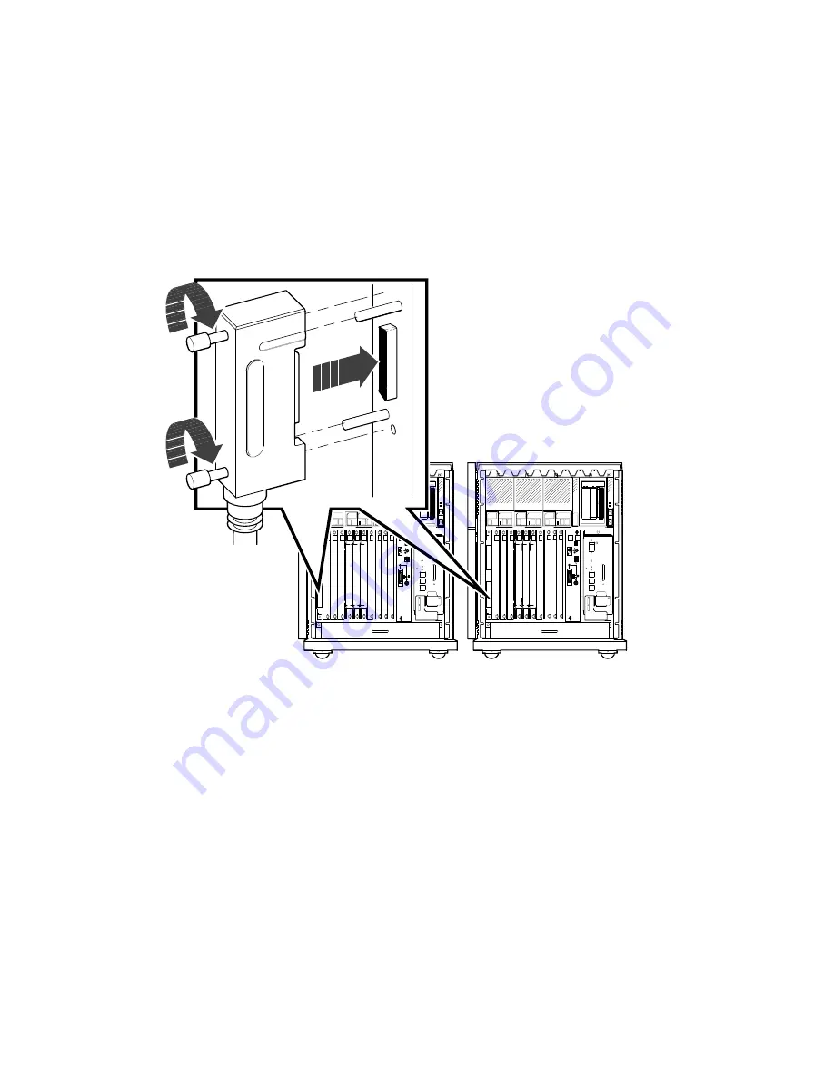
4. Feed either end of that cable under host A from the back or side. Then
insert the cable connector into the DSSI In/Out connector by fitting the
cable connector over the two guide pins shown in Figure 42.
Tighten the screws by hand, then use a screwdriver to secure the
connection.
Figure 42:
Connecting the DSSI Cable
Host A
MLO-005574
Host B
5. Repeat the previous step for host B using the opposite end of the DSSI
cable.
VAX 4000 Model 200 (BA430) Installation
61


