3 - 5
PL-6900 Series User Manual
Installing Optional Units and Expansion Boards
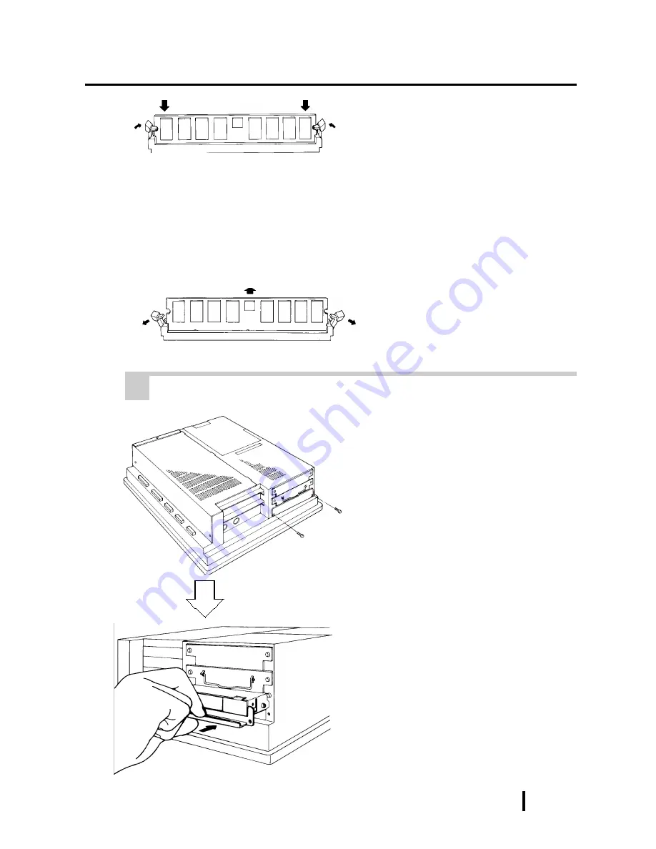
5) Push the DIM module down until
the side stoppers lock.
6) Replace the rear maintenance
cover and the half cover and secure
them in place with the attachment
screws.
To Remove the DIM Module
When removing the module from the socket, press down on the socket’s ejector
tabs to release the module.
3 Installing the FDD Unit (PL-FD200)
1) Remove the two(2) attachment
screws from the lowermost Expan-
sion Slot Cover, and remove the
cover.
2) Insert the FDD unit so that its guide
grooves fit the chassis guide ways.
Push the unit in until its rear con-
nector is connected securely.
3) Fix the unit in place with its two(2)
attachment screws.
(PL-6901T)
Summary of Contents for Pro-Face PL-6900 Series
Page 17: ...xvi Preface PL 6900 Series User Manual MEMO ...
Page 23: ...1 6 PL 6900 Series User Manual Overview MEMO ...
Page 51: ...3 14 PL 6900 Series User Manual Installing Optional Units and Expansion Boards MEMO ...
Page 61: ...4 10 PL 6900 Series User Manual Installation and Wiring MEMO ...
Page 81: ...6 4 PL 6900 Series User Manual OS Setup MEMO ...
Page 91: ...7 10 PL 6900 Series User Manual Maintenance and Inspection MEMO ...
Page 101: ...App 10 PL 6900 Series User Manual Appendix MEMO ...


