


1 3
A b o u t t h e D i g i C o n n e c t M E & D i g i C o n n e c t W i - M E E m b e d d e d M o d u l e s
Note
The development board provides a reference design of a POE (Power Over
Ethernet) power supply. A schematic for this reference design is installed by
the setup program on the CD.
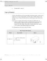
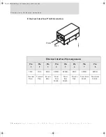
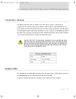
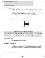
Connectors: Ethernet Interface
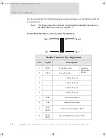
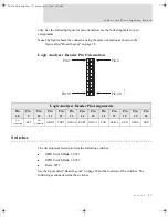
The
Ethernet connector is an 8-wire RJ-45 jack that meets the ISO 8877 requirements for
10/100BASE-T. See the following figure and table for pin orientation and pin assignments.
Note
Pin orientation and assignments are the same for modules with or without a
JTAG connector.
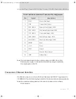
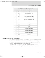
7
RXD
Receive Data (Input)
8
TXD
Transmit Data (Output)
9
RTS / GPIO 4
Request to Send (Output) / GPIO
10
DTR / GPIO 5
Data Terminal Ready (Output) / GPIO
11
CTS / GPIO 2
Clear to Send (Input) / GPIO
12
DSR / GPIO 3
Data Set Ready (Input) / GPIO
13
DCD / GPIO 1
Data Carrier Detect (Input) / GPIO
14
RESET
Reset
15
+3.3V
Power
16
GND
Ground
17-19
—
Reserved. Do not connect.
20
/INIT
Software Reset
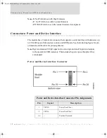
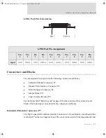
Power and Device Interface Connector Pin Assignments
Pin
Signal
Description
DC_ME-HWR.book Page 13 Thursday, July 1, 2004 11:12 AM
Summary of Contents for Digi Conntect ME
Page 1: ...TM TM 90000631_A DC_ME HWR book Page 1 Thursday July 1 2004 11 12 AM...
Page 2: ...DC_ME HWR book Page 2 Thursday July 1 2004 11 12 AM...
Page 4: ...DC_ME HWR book Page 4 Thursday July 1 2004 11 12 AM...
Page 63: ...DC_ME HWR book Page 63 Thursday July 1 2004 11 12 AM...
Page 64: ...DC_ME HWR book Page 64 Thursday July 1 2004 11 12 AM...


