

C o n n e c t o r s a n d B l o c k s
2 4
D i g i C o n n e c t W i - M E & D i g i C o n n e c t M E H a r d w a r e R e f e r e n c e
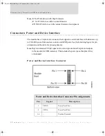
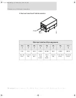
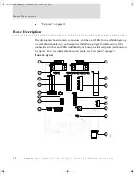
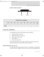
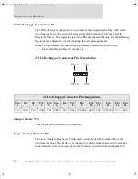
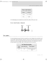
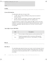
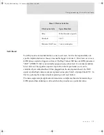
the development kit. See the following figure for pin orientation; see the following table for
pin assignments.
Note:
The figure shows the connector using the same orientation as shown in
the figure titled
"Board Layout" on page 18
.
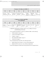
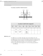
Embedded Module Connector Pin Orientation
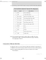
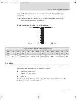
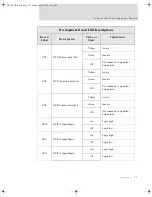
Module Connector Pin Assignments
Pin
Signal
Description
1
VETH+
Power Pass-Thru +
Unused on
Digi Connect
Wi-ME
2
VETH-
Power Pass-Thru -
3
—
Position Removed
4
—
Position Removed
5
—
Position Removed
6
—
Position Removed
7
RXD
Receive Data (Input)
8
TXD
Transmit Data (Output)
9
RTS /
GPIO-4
Request to Send (Output) / GPIO
10
DTR /
GPIO-5
Data Terminal Ready (Output) / GPIO
Pin 20
Pin 1
Pin 19
Pin 2
00000008
DC_ME-HWR.book Page 24 Thursday, July 1, 2004 11:12 AM
Summary of Contents for Digi Conntect ME
Page 1: ...TM TM 90000631_A DC_ME HWR book Page 1 Thursday July 1 2004 11 12 AM...
Page 2: ...DC_ME HWR book Page 2 Thursday July 1 2004 11 12 AM...
Page 4: ...DC_ME HWR book Page 4 Thursday July 1 2004 11 12 AM...
Page 63: ...DC_ME HWR book Page 63 Thursday July 1 2004 11 12 AM...
Page 64: ...DC_ME HWR book Page 64 Thursday July 1 2004 11 12 AM...


