

2 5
A b o u t t h e D e v e l o p m e n t B o a r d
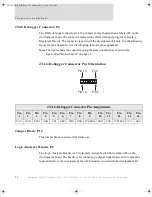
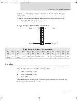
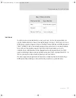
Module JTAG Interface Connector, P8
The Module JTAG Interface Connector is a 14-pin female vertical header that is labeled P8
on the development board. The connector mates with the JTAG connector on the Digi
Connect ME embedded module. The Module JTAG Connector pins are tied to the JTAG
debugger Connector (see “JTAG Debugger Connector, P4”).
Note
Because there is no direct connection to the Module JTAG Interface Connector,
pin orientation and pin assignments are not described for the connector.
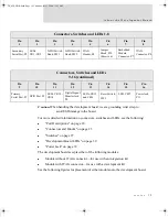
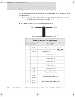
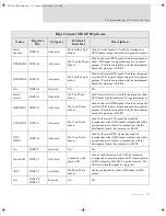
11
CTS /
GPIO-2
Clear to Send (Input) / GPIO
12
DSR /
GPIO-3
Data Set Ready (Input) / GPIO
13
DCD /
GPIO-1
Data Carrier Detect (Input) / GPIO
14
RESET
Reset
15
+3.3V
Power
16
GND
Ground
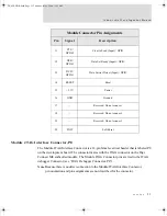
17
—
Reserved. Do not connect.
18
—
Reserved. Do not connect.
19
—
Reserved. Do not connect.
20
/INIT
Soft Reset
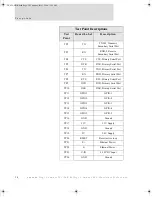
Module Connector Pin Assignments
Pin
Signal
Description
DC_ME-HWR.book Page 25 Thursday, July 1, 2004 11:12 AM
Summary of Contents for Digi Conntect ME
Page 1: ...TM TM 90000631_A DC_ME HWR book Page 1 Thursday July 1 2004 11 12 AM...
Page 2: ...DC_ME HWR book Page 2 Thursday July 1 2004 11 12 AM...
Page 4: ...DC_ME HWR book Page 4 Thursday July 1 2004 11 12 AM...
Page 63: ...DC_ME HWR book Page 63 Thursday July 1 2004 11 12 AM...
Page 64: ...DC_ME HWR book Page 64 Thursday July 1 2004 11 12 AM...


