


VECTORDRIVE DSV 5445
Top technology in drive electronics
07.07.04 10:12
Dietz-electronic
page 14 of 60
4 Control unit / Inputs and Outputs
4.1 Digital inputs and outputs
The inverter has freely programmable inputs and outputs as well as several fixed wired inputs and outputs.
This enables simple control tasks to be handled. A voltage of 30 V DC must not be exceeded under any cir-
cumstances on inputs and outputs. The control voltage must be smoothed with electrolytic capacitors.
Each output can handle a maximum current of 0.1A with a maximum voltage of 24 V DC. The power supply
to the outputs is via pin 11 and pin 12 on connector X1 from an external power source. The power supply
should have a 2AT fuse. Inputs operate with a voltage of 15 - 24 V DC. They require a current of 10 mA each.
The voltage relates to the frame earth terminal on pin 11 of connector X1.
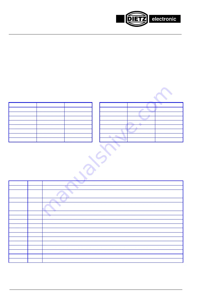
4.2 Freely programmable inputs and outputs on connector X2 (optional)
The freely programmable inputs and outputs are accessible on connector X2.
Treminal
Abbreviation
Assignment
Terminal
Abbreviation
Assignment
1
A7
Output 7
9
E7
Input 7
2
A6
Output 6
10
E6
Input 6
3
A5
Output 5
11
E5
Input 5
4
A4
Output 4
12
E4
Input 4
5
A3
Output 3
13
E3
Input 3
6
A2
Output 2
14
E2
Input 2
7
A1
Output 1
15
E1
Input 1
8
A0
Output 0
16
E0
Input 0
Each input can also be interrogated statically by means of flags. The addresses are given in the
section Pro-
gramming, Inputs
and
Outputs.
4.3 Fixed programmable inputs and outputs on connector X1
The fixed wired inputs on connector X1 are dominant. This means that the commands of a control program
are overridden, and a control program must be set accordingly. The supply conductors for the ISP, INT and
E8 signals and for the setpoint values must be screened to prevent any feedthrough.
The following functions are provided:
Terminal
Name
Function
2
A9 (SI) This output A9 is freely programmable
3
BB
Ready for operation. The output is set when the inverter and supply unit are ready for
operation. The signal is also displayed by the left LED on the front panel.
5
ISP
Pulse barrier, blocks the end stage of the inverter.
6
E8
Freely programmable input. If this input is not used, it must be set at 24 V (high) (see
section Programming, Blocks
)
8
INT
This input is used for an external transducer zero pulse.
11
0 V
Earth for external 24 V supply voltage
12
24 V
Connection for external 24 V supply voltage
19
1SW+
1st setpoint value "+"
17
1SW-
1st setpoint value "-"
18
SGND
Setpoint earth
25
2SW-
2nd setpoint value "-"
15
2SW+
2nd setpoint value "+"
20
+15 V
In15 V
22
-15 V
Internal -15 V
23
KMR
Thermistor input, input for motor temperature monitoring
24
KMH
Thermistor input, input for motor temperature monitoring
☞
Examples of terminal assignment for specified analog setpoint values can be found in the Ap-
pendix.


