


Elton User Manual Rev 1.04
Page 61
When the Flashing process is complete:
Power cycle the system and verify that the PTN3460 chip has retained the written values.
Set the GPIO to high-level mode.
Refer to Section 17.1
for scripting instructions on setting the GPIO to
high-level mode.
For other LVDS resolutions, refer to the respective display datasheets and set the registers accordingly.
Camera Installation Procedures
Similar to the Xavier Developer Kit Carrier Board, the Elton baseboard supports four MIPI CSI x4 camera
interfaces through a 120-pin daughterboard connector.
Synchronized-4k-cameras from
can be plugged into the daughterboard connector to
support the four 4-lane or six 2-lane cameras. The daughterboard connector also supports i2c and control
signals which enable users to directly interface the camera to the baseboard.
The following procedures use the e-CAM130_CUXVR MIPI-four-AR1335-module camera board to
demonstrate the installation and implementation of the cameras. The prebuild module drivers provided in the
e-CAM130_CUXVR package are loaded automatically during the boot.
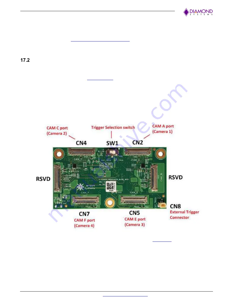
The e-CAM130_CUXVR is a multi-board set comprising of three board components as follows:
1.
The Camera Baseboard
(e-CAM30_HEXCUXVR_BASE_BRD)
Refer to the
e-CAM130_CUXVR_Getting_Started_Manual.pdf
on the
page located at the
e-con Systems site for detailed interfacing information
.


