Elton User Manual Rev 1.04
Page 24
USB 2.0 Port Connector: J20
The baseboard hosts two USB 2.0 ports The USB 2.0 interface connector features data and power pins on
a pin header. The shield pin is tied to the Chassis Ground.
The pinouts for the USB 2.0 connector are specified below.
Key A01 B01 Shield
USB1 Pwr-
A02 B02
USB0 Pwr-
USB1 Data+
A03 B03
USB0 Data+
USB1 Data-
A04 B04
USB0 Data-
USB1 Pwr+
A05 B05
USB0 Pwr+
Connector Type:
2mm Dual-Row Right Angle Pin Header
Mating Cable Part Number for Latching Connector:
6980602
Mating Cable Part Number for Pin Header:
6981082
PCIe/104 Connector: J1
The PCIe/104 connector is implemented to facilitate I/O expansion modules to plug into AGX Xavier Series
Module baseboards.
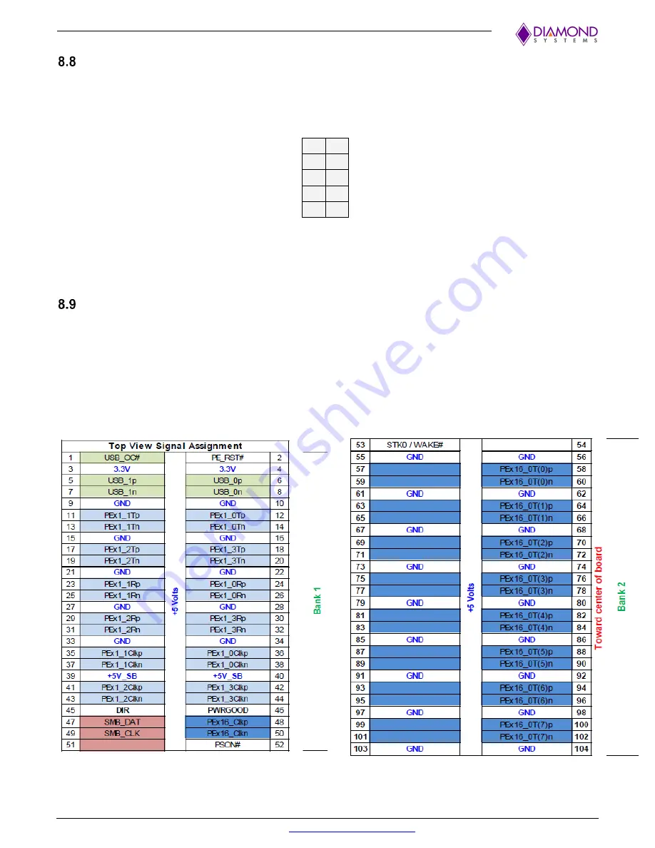
Four x1 PCIe lanes and two USB 2.0 ports are connected to the OneBank PCIe/104 connector.
One number of x8 lane PCIe from the AGX Xavier Series Module is connected to the 2nd and 3rd Bank of
the PCIe/104 connector.
The signal assignments for Banks 1 and 2 are depicted below.
Figure 8.9-1:Signal Assignment on Bank 1
Figure 8.9-2: Signal Assignment on Bank 2


