


E-DWT-10000-AF OPERATION AND MAINTENANCE MANUAL
© 2008 DH Instruments, a Fluke Company
Page 24
Rotate the variable volume CCW to the beginning of its stroke (position indicator
white, variable volume will no longer rotate).
Close the reservoir shut off valve.
Rotate the variable volume CW to generate pressure until the pressure reaches the
value recorded in step a. Use only the variable volume to adjust the pressure.
Slowly open the TEST shut off valve to reconnect the variable volume to the test
system. Proceed to continue to generate pressure as in 6.
To reduce pressure, rotate the variable volume CCW.
Opening the reservoir shut off valve while the E-DWT is under pressure will very rapidly drop
the pressure. Generally, it is not recommended to drop the pressure applied to pressure
measuring devices very rapidly. To reduce pressure slowly, use the variable volume and only open
the reservoir shut off valve to open the system to atmosphere.
3.5.3
PRESSURE FINE ADJUSTMENT, FINE ADJUST VALVE
To adjust pressure more precisely than is possible with the variable volume, the fine adjust
valve is used. When the valve is open, the displacement of its needle is used as a miniature
variable volume to adjust pressure.
The test isolation and fine adjust valve is a needle valve with a stroke of several millimeters.
Turn the valve handle CW to increase pressure CCW to decrease.
When using the fine adjust valve to adjust pressure, be sure not to close the valve so that the
E-DWT is no longer connected to the test system. If turning the valve handle or the variable
volume does not change the pressure indicated by both the RPM4-E-DWT AND the device
under test, the valve is closed.
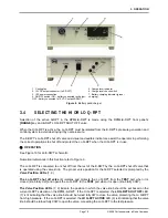
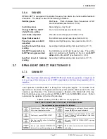
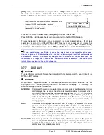
3.6
RPM4-E-DWT USER INTERFACE
The E-DWT-10000-AF’s RPM4-E-DWT A70M/A7M-AF reference pressure indicator is designed to offer
the optimum balance between simple, straight forward operation and the availability of a wide variety of
functions with a high level of operator discretion if desired.
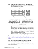
The RPM4-E-DWT’s local operator interface is through the front panel’s 2 x 20 character alpha-numeric
display, a function/data keypad, a cursor control pad and a
Ready/Not Ready
indicator. An optional
[ENTER]
footswitch is available. Remote communication is also available via the RS-232 (COM1)
interface (see Section 4).
The E-DWT mounts the RPM4-E-DWT at a convenient viewing angle and includes a valve and visual
indicators to isolate and protect the RPM4-E-DWT’s 1 000 psi Q-RPT (A7M) when using the 10 000 psi
Q-RPT (A70M) (see Section 3.4).
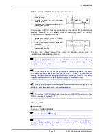
3.6.1
MAIN RUN SCREEN
The RPM4-E-DWT MAIN RUN screen is its home display that is reached on power-up and
from which other functions and menus are accessed. It is the very top level of all menu
structures.
The MAIN RUN screen is where RPM4-E-DWT is left in normal operation. It displays the
current measured pressure as well as a variety of additional information if desired.
Figure 11 and its legend summarize the RPM4-E-DWT MAIN RUN screen fields and their
functions.


