


4.2
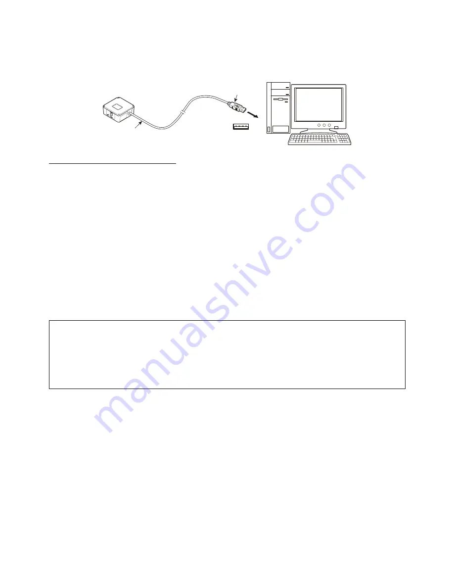
QB30-SU
The scanner receives and sends data from/to the host computer through the USB-COM interface or USB keyboard interface.
You need to set up the device driver designed for the interface to be used.
USB connector
Scanner
USB interface cable
Notes for connecting the USB interface cable
To use the USB-COM interface, you need to install the serial port driver to the host computer before connection of the USB
interface cable.
When plugging and unplugging the USB connector, put an interval of at least 10 seconds between those actions since
Windows may take several to 10 seconds to add or delete the USB device.
Hot plugging/unplugging is allowed for USB devices. However, do not plug or unplug the USB connector when:
- The computer is on standby (in suspend mode) or
- The COM port is open with the USB-COM interface being used. (Hot plugging/unplugging under this condition will lose
data.)
When the host computer is processing the scanner connection, do not plug or unplug any other USB device cables.
Directly connect the scanner to the USB port on the host computer or to the self-powered hub. The scanner may not be
connected to some types of hubs. If the operation of the hub-connected scanner is unstable, connect it directly to any USB
port on the host computer.
Do not use any extension cord.
Do not use the power management functions of the computer.
This device does not support power management functions such as “Standby”, “Sleep”, “Resume” and “Hibernation”.
Cancel the setting of those power management functions before setting up the device.
When suspend status is cancelled while the software for communication on the computer is open, occasionally computers
are unable to communicate.
In that case, please terminate the software and restart the computer.
6
Summary of Contents for QB30-SR
Page 1: ...2D Code Scanner Fixed type QB30 SR QB30 SU User s Manual...
Page 112: ...Terminator when transmitting None ETX CR LF CR LF 101...
Page 114: ...USB interface to the host USB COM interface default USB keyboard interface 103...
Page 123: ...Beeper control Disable Enable default Indicator LED Disable Enable default 112...


