


81
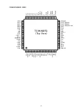
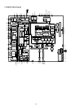
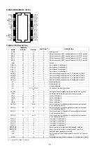
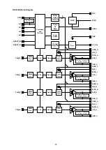
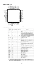
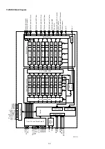
TC94A92FG
2009-05-27
7
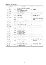
Pin
No.
Symbol I/O
Description
Default
Remarks
41
DVSS3R
-
Grounding pin for 3.3V Muiti-Bit DAC circuit
-
42
Ro
O
3AI/F
R channel audio output pin of Audio DAC.
O
43
DVDD3R
-
Power supply pin for 3.3V Audio DAC circuit.
-
44
DVDD3L
-
Power supply pin for 3.3V Audio DAC circuit.
-
45
Lo
O
3AI/F
L channel audio output pin of Audio DAC
O
46
DVSS3L
-
Grounding pin for 3.3V Muiti-Bit DAC Circuit
-
47
XVSS3
-
Grounding pin for 3.3V clock oscillator circuit
-
48
Xi
I
3AI/F
System clock Input pin
I
49
Xo
O
3AI/F
System clock Output pin
O
Xtal oscillation circuit.
Connect feedback resistor 1
M
Ω
between Xo and Xi
50
XVDD3 -
Power Supply pin for 3.3V clock
oscillator circuit
-
51
VDD1-2
-
Power Supply pin for 1.5V Digital circuit
-
52
VSS-2
-
Grounding pin for 1.5V digital circuit
-
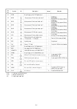
53
Pio0
I/O
3I/F
Port 0
(
General Input/Output Port
)
I
CMOS Port
Schmitt input
Refer to [1.2 Pin Assinment Table]
54
Pio1
I/O
3I/F
Port 1
(
General Input/Output Port
)
I
CMOS Port
Schmitt input
Refer to [1.2 Pin Assinment Table]
55
Pio2
I/O
3I/F
Port 2
(
General Input/Output Port
)
I
CMOS Port
Schmitt input
Refer to [1.2 Pin Assinment Table]
56
Pio3
I/O
3I/F
Port 3
(
General Input/Output Port
)
I
CMOS Port
Schmitt input
Refer to [1.2 Pin Assinment Table]
57
Pio4
I/O
3I/F
Port 4
(
General Input/Output Port
)
I
CMOS Port
Schmitt input
Refer to [1.2 Pin Assinment Table]
58
Pio5
I/O
3I/F
Port 5
(
General Input/Output Port
)
I
CMOS Port
Schmitt input
Refer to [1.2 Pin Assinment Table]
59
Pio6
I/O
3I/F
Port 6
(
General Input/Output Port
)
I
CMOS Port
Schmitt input
Refer to [1.2 Pin Assinment Table]
60
Pio7
I/O
3I/F
Port 7
(
General Input/Output Port
)
I
CMOS Port
Schmitt input
Refer to [1.2 Pin Assinment Table]
Summary of Contents for CEOL RCD-N8
Page 10: ...10 DIMENSION 299 0 112 0 108 0 35 0 35 0 210 0 280 0 2 0 301 0 218 0 45 0 36 0 30 0 4 0 ...
Page 22: ...22 3 Remove the screws 4 Remove the screws Shooting direction C Shooting direction A ...
Page 24: ...24 4 Remove the screws remove the connector wires CN221 CN222 Shooting direction C ...
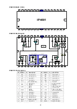
Page 84: ...84 PCM9211 MAIN IC103 ...
Page 85: ...85 PCM9211 Block Diagram ...
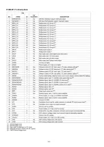
Page 86: ...86 PCM9211 Pin Discriptions ...
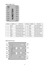
Page 87: ...87 NJM2755 MAIN IC701 NJM2755 Block Diagram ...
Page 93: ...93 L6565 SMPS IC821 L6565 Block Diagram ...
Page 94: ...94 ICE3BR1765J SMPS IC871 ICE3BR1765J Block Diagram ...


