


32
4.6. Accumulated laser on time display
When the Volume
f
button is pressed while this Unit is in the "CD TEST MODE "displayed, the accumulated laser on
time is displayed.
The laser drive times are added and the result is displayed.
One count corresponds to 10 minutes. The accumulated laser on time is displayed in hours. Displays up to 10922 hours.
Press the SOURCE button, CD TEST MODE display reappears.
The count values are not cleared, even when the set is reset (Factory/User).
Count value is reset
When the
1
/
3
ENTER button is pressed for over 5 seconds while the accumulated laser on time is displayed, the count
value is reset.
Count value is reset upon shipment from the factory and when the mechanism is replaced.
5. CD heat run mode
Heat run mode Startup display
"Heatrun Mode" displayed for 5 seconds.
Press the Cursor
u
/
i
button to switch the mode. (H.R. Normal, H.R. Short, H.R. Chacking)
After loading the disc, press
1
/
3
ENTER button.
While heat run, the operation of each button is not valid If an error occurs, display the error and stop operation at that
point. Refer to Heat run error code table.
To exit this mode, unplug the power cord.
5.1. Normal heat run mode
Playing from the first track to last track on disc. After disc playback has finished, then tray open and close. And playback
again.
The heat run repetition no. is incremented (increased by 1) when the tray is opened.
Repeat this operation.
[H.R. Normal] displayed.
Select "H.R.Normal", and press
1
/
3
ENTER button.
Press the Cursor
u
button to display the count.
Summary of Contents for CEOL RCD-N8
Page 10: ...10 DIMENSION 299 0 112 0 108 0 35 0 35 0 210 0 280 0 2 0 301 0 218 0 45 0 36 0 30 0 4 0 ...
Page 22: ...22 3 Remove the screws 4 Remove the screws Shooting direction C Shooting direction A ...
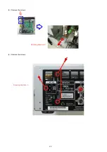
Page 24: ...24 4 Remove the screws remove the connector wires CN221 CN222 Shooting direction C ...
Page 84: ...84 PCM9211 MAIN IC103 ...
Page 85: ...85 PCM9211 Block Diagram ...
Page 86: ...86 PCM9211 Pin Discriptions ...
Page 87: ...87 NJM2755 MAIN IC701 NJM2755 Block Diagram ...
Page 93: ...93 L6565 SMPS IC821 L6565 Block Diagram ...
Page 94: ...94 ICE3BR1765J SMPS IC871 ICE3BR1765J Block Diagram ...


