


13
NOTE HANDLING AND REPLACEMENT OF THE LASER PICK-UP
1. Protection of the LD
Short a part of the LD circuit by soldering. After connection to a circuit, remove the short solder.
2. Precautions when handling the laser CD mechanism
• Handle the laser pick-up so that it is not exposed to dust.
• Do not leave the laser pick-up bare. Be sure to cover it.
• If dust adheres on lens of the pick-up, blow it off with a blower brush.
• Do not shock the laser pick-up.
• Do not watch the light of the laser pick-up.
3. Cautions on assembling and adjustment
• Be sure that to the bench, jig, head of soldering iron (with ceramic) and measuring instruments are well grounded.
• Workers who handle the laser pick-up must be grounded.
• The finished mechanism (prior to anchoring in the set) should be protected against static electricity and dust.
The mechanism must be stored that damaging outside forces are not received.
• When carrying the finished mechanism, hold it by the chassis body
• For proper operation, storage and operating environment should not contain corrosive gases. For example H2S, SO2,
NO2, CI2 etc. In addition storage environment should not have materials that emit corrosive gases especially from
silicic, cyanic, formalin and phenol group. I the mechanism or the set, existence of corrosive gases may cause no
rotation in motor.
4. Determining whether the laser pick-up is defective
• Check the Iop(Laser drive current). Check lop in "SPECIAL MODE". (Refer to 23 page.)
• If the present Iop (current) value becomes more than 50mA, replace the Traverse unit with a new one.
• No mechanical adjustment is necessary after the replacement.
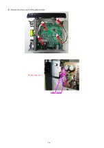
Protective soldering place for laser diode.
Summary of Contents for CEOL RCD-N8
Page 10: ...10 DIMENSION 299 0 112 0 108 0 35 0 35 0 210 0 280 0 2 0 301 0 218 0 45 0 36 0 30 0 4 0 ...
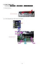
Page 22: ...22 3 Remove the screws 4 Remove the screws Shooting direction C Shooting direction A ...
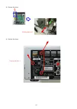
Page 24: ...24 4 Remove the screws remove the connector wires CN221 CN222 Shooting direction C ...
Page 84: ...84 PCM9211 MAIN IC103 ...
Page 85: ...85 PCM9211 Block Diagram ...
Page 86: ...86 PCM9211 Pin Discriptions ...
Page 87: ...87 NJM2755 MAIN IC701 NJM2755 Block Diagram ...
Page 93: ...93 L6565 SMPS IC821 L6565 Block Diagram ...
Page 94: ...94 ICE3BR1765J SMPS IC871 ICE3BR1765J Block Diagram ...


