


14
DISASSEMBLY
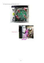
• Disassemble in order of the arrow in the following figure.
• In the case of the re-assembling, assemble it in order of the reverse of the following flow.
• In the case of the reassembling, observe "Caution concerning disassembly and assembly!".
• If wire bundles are untied or moved to perform adjustment or replace parts etc., be sure to rearrange them neatly as
they were originally bundled or placed afterward.
Otherwise, incorrect arrangement can be a cause of noise generation.
CAUTION:
Through great care is taken when manufacturing parts from sheet metal, there may in some rare cases be burrs on the
edges of top cover which could cause injury if fingers are moved across them. Use gloves to protect your hands.
SIDE PANEL
CD MECHA ASSY
Refer to
"DISASSEMBLY
2. CD MECHA ASSY"
and
"EXPLODED VIEW"
CD MECHA ASSY
(Ref. No. of EXPLODED VIEW : 10)
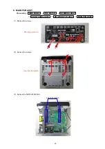
MAIN PCB ASSY
Refer to
"DISASSEMBLY
2. MAIN PCB ASSY"
and
"EXPLODED VIEW"
MAIN PCB ASSY
(Ref. No. of EXPLODED VIEW : P2)
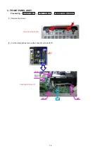
FRONT PANEL ASSY
Refer to
"DISASSEMBLY
3. FRONT PANEL ASSY"
and
"EXPLODED VIEW"
FRONT PANEL ASSY
(Ref. No. of EXPLODED VIEW : 2)
SMPS PCB ASSY
Refer to
"DISASSEMBLY
4. SMPS PCB ASSY"
and
"EXPLODED VIEW"
SMPS PCB ASSY
(Ref. No. of EXPLODED VIEW : P6)
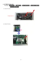
NETWORK PCB ASSY
Refer to
"DISASSEMBLY
4. NETWORK PCB ASSY"
and
"EXPLODED VIEW"
NETWORK PCB ASSY
(Ref. No. of EXPLODED VIEW : P5)
TOP COVER
Refer to
"DISASSEMBLY
1. TOP COVER"
and
"EXPLODED VIEW"
TOP COVER
(Ref. No. of EXPLODED VIEW : 21)
Summary of Contents for CEOL RCD-N8
Page 10: ...10 DIMENSION 299 0 112 0 108 0 35 0 35 0 210 0 280 0 2 0 301 0 218 0 45 0 36 0 30 0 4 0 ...
Page 22: ...22 3 Remove the screws 4 Remove the screws Shooting direction C Shooting direction A ...
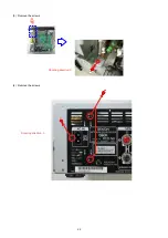
Page 24: ...24 4 Remove the screws remove the connector wires CN221 CN222 Shooting direction C ...
Page 84: ...84 PCM9211 MAIN IC103 ...
Page 85: ...85 PCM9211 Block Diagram ...
Page 86: ...86 PCM9211 Pin Discriptions ...
Page 87: ...87 NJM2755 MAIN IC701 NJM2755 Block Diagram ...
Page 93: ...93 L6565 SMPS IC821 L6565 Block Diagram ...
Page 94: ...94 ICE3BR1765J SMPS IC871 ICE3BR1765J Block Diagram ...


