


31
4.4. All servo on and Auto Adjustment
When Cursor
u
button is pressed, all servos turn on, auto adjustment is performed and switch to playback operation.
(Playback sound output)
Stop (stop to the playback state after auto adjustment)
When SOURCE button is pressed, play operation and servo stop. The following will be displayed.
After stopping, conduct reading of auto adjust values.
Adjustment value display (After All Servo on and Auto Adjustment)
Press the SOURCE button, after All servo on and Auto Adjustment.
When Cursor
u
/
i
button is pressed, the adjustment values are displayed in the following order.
q
FOCUS BALANCE
w
FOCUS GAIN
e
TRACKING BALANCE
r
TRACKING GAIN
t
FOCUS OFFSET
y
TRACKING OFFSET
u
RFRP
(Caution) If you have not completed the adjustment, the value is not correct.
4.5. All servo on and auto adjustment.
When VOLUME
d
button is pressed for over 1 second while the Unit is in the CD TEST MODE, the laser turns on and
the laser current is measured.
The laser drive current undergoes A/D conversion for calculation. The decimal point is omitted.
The current value is updated every 3 seconds.
Press the SOURCE button, CD TEST MODE display reappears.
Stored data is not cleared, even when the Unit is reset(Factory/User).
Overwriting the stored data
When the
1
/
3
ENTER button is pressed for over 5 seconds while the laser current is displayed, the current value is
stored in the EEPROM (overwriting the stored data).
Once rewriting is completed, the display in "Laser current display" reappears. Rewriting is performed upon shipment from
the factory and when the mechanism is replaced.
Summary of Contents for CEOL RCD-N8
Page 10: ...10 DIMENSION 299 0 112 0 108 0 35 0 35 0 210 0 280 0 2 0 301 0 218 0 45 0 36 0 30 0 4 0 ...
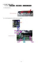
Page 22: ...22 3 Remove the screws 4 Remove the screws Shooting direction C Shooting direction A ...
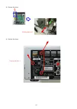
Page 24: ...24 4 Remove the screws remove the connector wires CN221 CN222 Shooting direction C ...
Page 84: ...84 PCM9211 MAIN IC103 ...
Page 85: ...85 PCM9211 Block Diagram ...
Page 86: ...86 PCM9211 Pin Discriptions ...
Page 87: ...87 NJM2755 MAIN IC701 NJM2755 Block Diagram ...
Page 93: ...93 L6565 SMPS IC821 L6565 Block Diagram ...
Page 94: ...94 ICE3BR1765J SMPS IC871 ICE3BR1765J Block Diagram ...


