background image

49

ENGLISH

Basic version

Simple version

Information

Advanced version

Input Setup

Source Level

Default settings are underlined.

• This function corrects the playback level of the selected input source’s audio input.
• Make this setting if there are differences in the input volume levels between the different sources.

Setting details

–12dB – +12dB (0dB)

 The  analog  input  level  and  digital  input  level  can  be  adjusted  independently  for  input  sources  for 

which “HDMI” or “Digital” is assigned at “Input Assign“ (

v

page 46).

Playback Mode

Setting items

Setting details

Repeat

Make settings for repeat 
mode.

DOCK


USB/iPod


n

For iPod playback
All

 : All files are played repeatedly.

One

 : A file being played is played repeatedly.

OFF

 : Repeat playback mode is canceled.


n

For USB memory device playback
All

 : All files are played repeatedly.

One

 : A file being played is played repeatedly.

Folder

 : A file in the folder being played is played repeatedly.

Shuffle

Make settings for shuffle 
mode.

DOCK


USB/iPod


n

For iPod playback 

(When iPod (USB/iPod), DENON control dock for 

iPod ASD-1R or ASD-11R is connected)

Songs

 : Shuffle songs.

Albums

 : Shuffle albums. 

OFF

 : Shuffle playback mode is canceled.


n

For iPod playback

 (When DENON control dock for iPod ASD-3N, ASD-

3W, ASD-51N or ASD-51W is connected)

ON

 : Shuffle playback mode is enabled.

OFF

 : Shuffle playback mode is canceled.


n

For USB memory device playback
ON

 : Shuffle playback mode is enabled.

OFF

 : Shuffle playback mode is canceled.

Remote control operation 

buttons

Move the cursor 
(Up/Down/Left/Right)

Confirm the setting

Return to previous menu

Audio/Video Adjust

The sound being played in the surround mode can be adjusted to your liking. 
The items (parameters) that can be adjusted depend on the signal being input and the currently 
set surround mode. For details on the adjustable parameters, see “Surround modes and surround 
parameters” (

v

page 73).

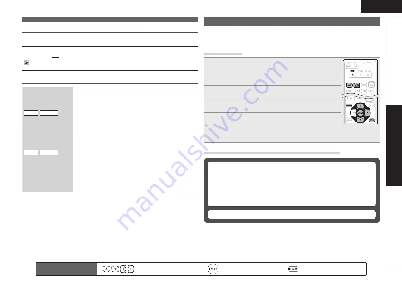
Menu operation

1

Press 

ZONE SELECT

 to switch the zone mode to “MAIN”. 

The “MAIN” indicator lights. 

2

Press 

AMP

 to set the remote control unit to amplifier operation 

mode.

3

Press 

MENU

.

The menu is displayed on the TV screen.

4

Press 

ui

 to select the menu to be set or operated.

5

Press 

ENTER

 or 

p

 to enter the setting.

• To return to the previous item, press 

RETURN

.

• Exiting the Menu, press 

MENU

 while the menu is displayed.

The menu display disappears.

Items that can be set with the Audio/Video Adjust procedure

Audio Adjust 

(

v

page 50)


n

Surround Parameter 

(

v

page 50)


n

Tone 

(

v

page 51)


n

Audyssey Settings 

(

v

page 52)


n

Manual EQ 

(

v

page 53)


n

RESTORER 

(

v

page 54)


n

Audio Delay 

(

v

page 54)

Picture Adjust 

(

v

page 54)

Summary of Contents for AV SURROUND RECEIVER AVR-891

Page 1: ...n Version simplifiée Versión sencilla v 3 Basic version Version basique Versión básica v 12 Advanced version Version avancée Versión avanzada v 29 Information Part names and functions vpage 68 v 67 Informations Nomenclature et fonctions vpage 68 Información Nombres y funciones de las piezas vpágina 68 ...

Page 2: ...rom tip over 13 Unplug this apparatus during lightning storms or when unused for long periods of time 14 Refer all servicing to qualified service personnel Servicing is required when the apparatus has been damaged in any way such as power supply cord or plug is damaged liquid has been spilled or objects have fallen into the apparatus the apparatus has been exposed to rain or moisture does not oper...

Page 3: ...midité Ne pas poser d objet contenant du liquide par exemple un vase sur l appareil Ne pas manipuler le cordon d alimentation avec les mains mouillées Lorsque l interrupteur est sur la position OFF l appareil n est pas complètement déconnecté du SECTEUR MAINS L appareil sera installé près de la source d alimentation de sorte que cette dernière soit facilement accessible Evite altas temperaturas Pe...

Page 4: ...ecorder 17 Connecting a digital camcorder 17 Connecting a control dock for iPod 18 Connecting an iPod or USB memory device to the USB Port 18 Connecting a CD player 19 Connecting an antenna 19 Playback Basic operation 20 Important information 20 Playing a Blu ray Disc player DVD player 21 Playing a CD player 21 Playing an iPod 21 Tuning in radio stations 24 Playing a USB memory device 25 Selecting...

Page 5: ...lso supports the ARC Audio Return Channel function which reproduces TV sound with this unit via an HDMI cable used for connecting the unit and a TVz z z The TV should support the ARC function 6 HDMI inputs and 1 output The unit is equipped with 6 HDMI input connectors for connecting devices with HDMI connectors such as a Blu ray Disc player game machine HD video camera etc High Definition Audio Su...

Page 6: ...it turn off the power to all devices n n For operation of the connected devices refer to the user manuals for each device Play back disc vpage 11 Enjoy Blu ray Disc and DVD in surround sound 5 Set up speakers vpage 6 Use the setup microphone DM A409 included with the product for automatic setup 4 Turn on power vpage 6 3 Connect vpage 4 Connect 5 1 channel speakers a TV and Blu ray Disc player equi...

Page 7: ...er terminals while the power supply is connected Doing so could result in electric shock Use speakers with the speaker impedances shown below Speaker terminals Speaker impedance FRONT 6 16 Ω CENTER SURROUND SURR BACK AMP ASSIGN Install 1 2 4 5 3 This unit can perform 2 0 2 1 to 7 1 channel surround playback Here we explain setup using the example of 5 1 channel speaker playback FL FR SW C SL SR 12...

Page 8: ...use High Speed HDMI cable or High Speed HDMI cable with Ethernet for enhanced high quality playback IN HDMI OUT HDMI To household power outlet AC 120 V 60 Hz Power cord included HDMI cable sold separately HDMI cable sold separately Blu ray Disc player TV NOTE Do not plug in the power cord until all connections have been completed Do not bundle power cords together with connection cables Doing so c...

Page 9: ... televisions radios air conditioners fluorescent lights home appliances light dimmers or other devices as measurements may be affected by these sounds Cell phones should be placed away from all audio electronics during the measurement process as Radio Frequency Interference RFI may cause measurement disruptions even if the cell phone is not in use Do not unplug the setup microphone from the main u...

Page 10: ...lue for the subwoofer The Simple version describes the installation connection and setup methods for 5 1 channel speakers See page 30 for the installation connection and setup methods for speakers other than 5 1 channel speakers Set up speakers Audyssey Auto Setup 2 Set up the subwoofer If using a subwoofer capable of the following adjustments set up the subwoofer as shown below n n When using a s...

Page 11: ...peration mode Press AMP to set the remote control unit to amplifier operation mode Press AMP 4 Connect the setup microphone to the SETUP MIC jack of this unit 1 6 STEP1 Preparation Connect the speakers and place them accord ing to the recommenda tions in the manual Set the following items if necessary Start Auto Setup Amp Assign Channel Select Auto Setup Start AUTO SETUP AUDYSSEY AUTO SETUP MultEQ...

Page 12: ...tance Check Ch Level Check Crossover Check Next Store AUTO SETUP AUDYSSEY AUTO SETUP MultEQ ENTER Enter RETURN Cancel Subwoofers may measure a greater reported distance than the actual distance due to added electrical delay common in subwoofers If you want to check another item press RETURN 13Use ui to select Next 1 Store and then press ENTER STEP 6 Store 14Select Store and then press ENTER Save t...

Page 13: ...ections Examples Error details Measures Caution No microphone or Speaker Retry Check cause of problem AUTO SETUP AUDYSSEY AUTO SETUP MultEQ RETURN Cancel The connected setup microphone is broken or a device other than the supplied setup microphone is connected Not all speakers could be detected The front L speaker was not properly detected Connect the included setup microphone to the SETUP MIC jac...

Page 14: ... 3 Adjust the sound volume VOL d Volume up VOL f Volume down MUTE Muting 4 Set the listening mode Set the listening mode according to the playback contents cinema music etc or according to your liking vpage 26 Selecting a listening mode Surround mode When power is switched to standby Press POWER OFF GPower indicator status in standby modeH Normal standby Off When HDMI Control is set to ON Red You ...

Page 15: ...y Disc player vpage 14 vpage 21 DVD player vpage 14 16 vpage 21 Set top box Satellite tuner or cable TV vpage 14 16 Digital video recorder vpage 14 17 Game console vpage 14 Digital camcorder vpage 14 17 Control dock for iPod vpage 18 vpage 21 Audio Playback Connection iPod vpage 18 vpage 22 USB memory device vpage 18 vpage 25 CD player vpage 19 vpage 21 Radio vpage 19 vpage 24 For speaker connecti...

Page 16: ...e output at 1080p regardless of the setting Resolutions of HDMI compatible TVs can be checked at HDMI Monitor Information vpage 62 NOTE HDMI signals cannot be converted into analog signals When a non standard video signal from a game machine or some other source is input the video conversion function might not operate Component video input signals cannot be converted into Video format A menu is ou...

Page 17: ...RGB color Adobe YCC601color vpage 78 79 High definition digital audio format ARC Audio Return Channel Content Type CEC HDMI control Copyright protection system In order to play back digital video and audio such as BD Video or DVD Video via HDMI connection both this unit and TV or the player need to support the copyright protection system known as HDCP High bandwidth Digital Content Protection Syst...

Page 18: ... on the combination of devices the video signals may not be output n n Settings related to HDMI connections Set as necessary For details see the respective reference pages Input Assign vpage 46 Set this to change the HDMI input connector to which the input source is assigned HDMI Setup vpage 58 Make settings for HDMI video audio output RGB Range Auto Lip Sync HDMI Audio Out HDMI Control Standby So...

Page 19: ...onnector to which the input source is assigned Input Assign vpage 46 in Set as Necessary Connecting a set top box Satellite tuner cable TV You can watch satellite or cable TV Select the connector to use and connect the device For instructions on HDMI connections see Connecting an HDMI compatible device vpage 14 Cables used for connections Video cable sold separately Video cable Yellow Component vi...

Page 20: ... video signals through this unit use the same type of video cable for connection between this unit and the player as used for connection between this unit and the recorder Connecting a digital camcorder You can enjoy video and audio from a digital comcorder You can enjoy games by connecting a game machine via the V AUX input connector In this case select the input source to V AUX For instructions ...

Page 21: ...SB memory device to the USB Port You can enjoy music stored on the iPod or USB memory device Cables used for connections To connect an iPod to this unit use the USB cable supplied with the iPod USB memory device iPod or When you want to playback a video file stored on an iPod use the DENON control dock for iPod ASD 1R ASD 11R ASD 3N ASD 3W ASD 51N and ASD 51W sold separately vpage 18 Connecting a ...

Page 22: ...und AM outdoor antenna AM loop antenna supplied Black White FM indoor antenna supplied n n AM loop antenna assembly 1 Put the stand section through the bottom of the loop antenna from the rear and bend it forward Stand Square hole Projecting part Loop antenna 2 Insert the projecting part into the square hole in the stand n n Using the AM loop antenna To use suspended on a wall Suspend directly on ...

Page 23: ...ted q w e q Input Source The name of the highlighted input source is displayed w Recently used sources The recently used input sources up to five are displayed e Icons for the input sources in the different categories are displayed w Use uio p to select the input source then press ENTER The input source is set and the source selection menu is turned off When using with an iPod connected directly t...

Page 24: ...iPod to this unit vpage 18 Connecting a control dock for iPod w Set the iPod in the DENON control dock for iPod 2 Press POWER ON to turn on power to the unit 3 Press DOCK to switch the input source to DOCK If Browse mode is selected in step 4 the following screen is displayed on a TV screen depending on the connected control dock for iPod When using an ASD 1R When using an ASD 11R iPod Music Video...

Page 25: ... the iPod n n Viewing videos on an iPod in the Browse mode When an iPod equipped with a video function is connected to a DENON ASD 11R ASD 3N ASD 3W ASD 51N and ASD 51W control dock for iPod image files can be played in the Browse mode 1 Use ui to select Videos then press ENTER or p 2 Use ui to select the search item or folder then press ENTER or p 3 Use ui to select the video file then press ENTE...

Page 26: ...search starts If you press and hold ui manual search starts z2 If you press ENTER during playback playback pauses If ENTER is pressed during pause playback resumes If you press and hold ENTER playback stops z3 This functions when an ASD 1R ASD 11R is used Press SEARCH then press o previous page or p next page To cancel press ui or SEARCH The time default 30 sec for which the menus are displayed ca...

Page 27: ...eturn to the original screen n n Listening to preset stations 1 Press SHIFT to select the memory block A to G 2 Press CH CH or 1 8 to select the desired preset channel You can also operate via the main unit In this case perform the following operations Press TUNINGPRESET then turn SOURCE SELECT to select the preset radio station n n Direct frequency tuning You can enter the receiving frequency dir...

Page 28: ...ns Function MENU Amp menu uio p Cursor operationz1 ENTER Enterz2 SEARCH Page Searchz3 RETURN Return 6 7 Press and hold Manual search fast reverse fast forward 1 Playback Pause 8 9 Auto search cue 3 Pause 2 Stop RESTORER RESTORER TV POWER TV power on standby Default SONY TV INPUT Switch TV input Default SONY Repeat playback vpage 49 Repeat Shuffling playback vpage 49 Shuffle z1 If you press ui duri...

Page 29: ...d playback The sound is played according to the settings of the speaker size in Speaker Config vpage 55 Surround back channel or front height channel signals that are not recorded in source can be created 2 channel Multi channel Surround DENON original surround playback vpage 28 The surround effects suitable for the source type or according to your liking can be selected from the DENON original so...

Page 30: ...IGITAL Plus DOLBY DIGITAL DOLBY DIGITAL Plus EX DOLBY D EX DOLBY DIGITAL Plus PLgx CINEMA DOLBY D PL x C DOLBY DIGITAL Plus PLgx MUSIC DOLBY D PL x M DOLBY DIGITAL Plus PLgz HEIGHT DOLBY D PL z DOLBY TrueHD DOLBY TrueHD DOLBY TrueHD DOLBY TrueHD EX DOLBY HD EX DOLBY TrueHD PLgx CINEMA DOLBY HD PL x C DOLBY TrueHD PLgx MUSIC DOLBY HD PL x M DOLBY TrueHD PLgz HEIGHT DOLBY HD PL z DTS 5 1ch DTS ES Di...

Page 31: ...sources recorded in monaural in the MONO MOVIE mode the sound will be off balance with a single channel left or right so input to both channels Depending on the program source being played it may not be possible to achieve a satisfactory surround effect In this case try other modes to achieve a sound field suited to your tastes NOTE When the input signal is Dolby TrueHD Dolby Digital Plus DTS HD o...

Page 32: ... Other than 5 1 channel vpage 30 F Playback Advanced operation vpage 36 F Playback in ZONE2 Separate room vpage 39 F How to make detailed settings vpage 41 F Operating the connected devices by remote control unit vpage 63 Advanced version Here we explain functions and operations that let you make better use of this unit ...

Page 33: ... in a position 2 to 3 ft 60 to 90 cm higher than ear level z Surround speaker 2 3 ft 60 90 cm GViewed from the sideH Front height speaker Point slightly downwards At least 3 3 ft 1 m Surround back speaker Point slightly downwards Front speaker z z Recommended for Dolby Pro Logic gz NOTE It is not possible to use the surround back speakers and front height speakers simultaneously When 7 1ch Front h...

Page 34: ...ront Height FL FR FHR FHL C SW SL SR 7 1 channel 6 1 channel Surround back speaker connection For 7 1 channel Surround back speaker playback set Amp Assign in Set up speakers vpage 34 to Normal FL FR C SBL SBR SL SR SW 6 1 channel connection If using just one surround back speaker with a 6 1 channel connection connect to the L side of the SURR BACK AMP ASSIGN terminal For speaker settings in this ...

Page 35: ... The second set of front speakers can be connected to the SURR BACK AMP ASSIGN terminals In this case set Amp Assign of Set up speakers vpage 34 to Front B FL A FL B FR B FR A SW For surround playback of a multichannel source if you connect the center speaker surround speakers and subwoofers 5 1 channel playback is available Front speakers can be used separately depending on the speaker s specific...

Page 36: ... surround speakers and subwoofers 5 1 channel playback is available NOTE Use speakers compatible with bi amp connections When making bi amp connections be sure to remove the short circuiting plate or wire between the speaker s woofer and tweeter terminals For speaker impedance and speaker cable connections see page 4 5 1 channel 2 1 channel connection If front speakers for 2 channel playback are c...

Page 37: ... ASSIGN terminals Here we describe how to set up speakers other than 5 1 channel speakers For the method of setting up 5 1 channel speakers see Simple version Set up speakers Audyssey Auto Setup vpage 6 First install and connect the speakers to this unit Before Auto Setup measurement the settings shown below can be made Changing the amplifier assignment Amp Assign The signal output from the SURR B...

Page 38: ... step 8 Surround Back Select for no surround back speakers to be used In this case go to step 9 Surround Back can be set when Amp Assign is set to Normal 7 GWhen Front is selected in step 6H Press o p to select a front speaker A Select this to use front speaker A B Select this to use front speaker B A B Select this to use front speakers A and B simultaneously Set up speakers 8 GWhen Subwoofer is s...

Page 39: ...erOffControl onthemenuissetto OFF vpage58 this unit is not set to standby even if the connected device is in the standby mode When connection changes are implemented such as adding connections to HDMI devices linked operations may be initialized In this case you will need to reconfigure the settings When HDMI Control is set to ON it is not possible to assign an HDMI connector to TV at Input Assign...

Page 40: ...amplifier operation mode 3 Press CH LEVEL Front L Front R Center Subwoofer Surround L Surround R S Back L S Back R Fader 0 0dB 0 0dB 0 0dB 0 0dB 0 0dB 0 0dB 0 0dB 0 0dB CHANNEL LEVEL Select Front Rear 4 Use ui to select the speaker The speaker that can be set switches each time one of the buttons is pressed 5 Use o p to adjust the volume In the case of a subwoofer pressing o when it is at 12 dB wi...

Page 41: ...SOURCE SELECT until RECOUT Source is displayed The indicator illuminates ZONE2 Source ZONE2 TUNER ZONE2 USB iPod RECOUT USB iPod RECOUT DOCK RECOUT Source 3 Turn SOURCE SELECT to choose the input source to be recorded For operating instructions refer to the respective equipment s operating instructions To record FM or AM broadcasts select the broadcast vpage 24 4 Start recording For operating inst...

Page 42: ...gnal Stereo L R MAIN ZONE ZONE2 This unit We recommend using high quality pin plug cables for audio connections in order to prevent noise NOTE It is not possible to play the digital audio signals input from the HDMI COAXIAL or OPTICAL connectors in ZONE2 Use analog connections for ZONE2 playback Video output is not available in ZONE2 Convenient functions Various memory functions n n Personal memor...

Page 43: ...be turned on or off by pressing ZONE2 ON OFF on the main unit 4 Press the input source select button The audio signal of the selected source is output to ZONE2 Turn SOURCE SELECT after pressing ZONE2 REC SELECT on the main unit to select an input source When power for both MAIN ZONE and ZONE2 is set to ON power of the MAIN ZONE only can be turned off Select MAIN in step 1 then press ZONE DEVICE OF...

Page 44: ...yssey Auto Setup measurement results This item is only displayed after Audyssey Auto Setup procedure has been performed 10 4 Manual Setup Make detailed speaker settings Speaker Setup HDMI Setup Audio Setup ZONE2 Setup Option Setup MANUAL SETUP Speaker Setup Sets the speaker size and distance the channel level etc 55 HDMI Setup Make settings for HDMI video audio output 58 Audio Setup Make settings ...

Page 45: ...n Default HDMI1 HDMI2 None HDMI3 HDMI4 HDMI5 HDMI6 HDMI None Coax1 Opt1 Coax2 Opt2 None None DIGITAL None 1 RCA None 2 RCA None None None COMP INPUT SETUP INPUT ASSIGN e Press ENTER q Input Assign BD HDMI1 e Input Assign BD HDMI1 Press ENTER q Use uio p to move to the item you want to set w Press ENTER to set to the mode in which the setting can be made e 0 1 is displayed at the sides of items who...

Page 46: ...t u v 8 G H I g h i 4 W X Y Z w x y z 9 J K L j k l 5 0 Space The input character type can be switched by pressing SHIFT while the display name is being changed For entering the characters assigned to one number button continuously press p to move the cursor to the right after entering a character then enter the next character For entering characters assigned to separate buttons press the number b...

Page 47: ...case characters Numbers SymbolsH ABCDEFGHIJKLMNOPQRSTUVWXYZ 0123456789 GLower case characters Numbers SymbolsH abcdefghijklmnopqrstuvwxyz 0123456789 _ The input character type can be switched by pressing SHIFT while the display name is being changed 5 Repeat steps 3 and 4 to change the name 6 Use uio p to select OK then press ENTER Remote control operation buttons Move the cursor Up Down Left Righ...

Page 48: ...uto INPUT SETUP INPUT MODE Automatically detect input signal and playback RETURN Return Repeat Shuffle All OFF INPUT SETUP PLAYBACK MODE Repeat all songs RETURN Return Auto Preset vpage 45 Input Assign vpage 46 Rename vpage 48 Video vpage 47 Source Level vpage 49 Input Mode vpage 48 Playback Mode vpage 49 Preset Skip vpage 45 Preset Name vpage 46 Remote control operation buttons Move the cursor Up...

Page 49: ... SAT CBL DVR GAME V AUX DOCK HDMI 1 HDMI 2 HDMI 3 HDMI 4 HDMI 5 HDMI 6 None Do not assign an HDMI input connector to the selected input source At time of purchase the settings of the different input sources are as shown below Input source BD DVD TV SAT CBL DVR GAME V AUX DOCK Default setting HDMI 1 HDMI 2 None HDMI 3 HDMI 4 HDMI 5 HDMI 6 None An input source to which an HDMI input connector cannot...

Page 50: ...t Source Delete vpage 60 cannot be selected Setting items Setting details Video Mode Make settings for video processing BD z DVD TV z SAT CBL DVR GAME z V AUX DOCK Auto Process video automatically based on the HDMI content information Movie Process video normally Game Always process video appropriate for game content If Video Mode is set to Auto the mode is switched according to the input contents...

Page 51: ...nything other than OFF z z BD TV or GAME can be set when HDMI vpage 46 or Component vpage 47 has been assigned Input Mode Default settings are underlined The input modes available for selection may vary depending on the input source Setting items Setting details Input Mode Set the audio input modes for the different input sources Auto Automatically detect input signal and perform playback HDMI Pla...

Page 52: ...k When DENON control dock for iPod ASD 3N ASD 3W ASD 51N or ASD 51W is connected ON Shuffle playback mode is enabled OFF Shuffle playback mode is canceled n n For USB memory device playback ON Shuffle playback mode is enabled OFF Shuffle playback mode is canceled Remote control operation buttons Move the cursor Up Down Left Right Confirm the setting Return to previous menu Audio Video Adjust The s...

Page 53: ...values below Dolby Digital sources 0dB DTS movie sources 0dB DTS music sources 10dB C Image Assign center channel signal to front left and right channels for wider sound 0 0 1 0 0 3 Remote control operation buttons Move the cursor Up Down Left Right Confirm the setting Return to previous menu Setting items Setting details Panorama Assign front L R signal also to surround channels for wider sound O...

Page 54: ...e S Back is not displayed F Height Determine whether to use front height channel ON Audio is output from the front height speaker OFF Audio is not output from the front height speaker NOTE F Height is displayed for the following settings When Amp Assign vpage 55 is set to Front Height When the Speaker Config F Height setting vpage 56 is set to other than None F Height cannot be set if the HD Audio...

Page 55: ... this setting NOTE MultEQ and Manual cannot be selected when EQ Customize is set to Not Used vpage 59 When using headphones MultEQ is automatically set to OFF Setting items Setting details Dynamic EQ Solve the problem of deteriorating sound quality as volume is decreased by taking into account human perception and room acoustics ON Use Dynamic EQ OFF Do not use Dynamic EQ is displayed when set to ...

Page 56: ...lume Evening Dynamic EQ ON Dynamic Volume OFF Dynamic EQ OFF Dynamic Volume OFF Dynamic EQ ON Dynamic Volume Day GOperations with the main unitH Press DYNAMIC VOLUME Each time DYNAMIC VOLUME is pressed the setting is changed as shown below Dynamic Volume Midnight Dynamic Volume Evening Dynamic Volume OFF Dynamic Volume Day n n Manual EQ Default settings are underlined Use the graphic equalizer to ...

Page 57: ...the remote control unit or the main unit makes this setting OFF Mode 1 RESTORER 64 Mode 2 RESTORER 96 Mode 3 RESTORER HQ n n Audio Delay Default settings are underlined While viewing video manually adjust the time to delay audio output Setting details 0ms 200ms This item can be set within the range of 0 to 100 ms when Auto Lip Sync is set to ON and when a TV compatible with Auto Lip Sync is connec...

Page 58: ...not be possible to select MultEQ Dynamic EQ and Dynamic Volume vpage 52 53 Manual Setup can be used without changing the settings Please set if necessary Setting items Setting details Amp Assign Set the speakers connected to this unit Normal Set when using 7 1 channel Front Center Surround Surround Back Subwoofer speakers ZONE2 Set for connecting the speakers for ZONE2 to the SURR BACK AMP ASSIGN ...

Page 59: ...rence in the distance between the speakers to less than 20 ft 6 0 m NOTE Speakerssetto None in SpeakerConfig vpage55 arenotdisplayed Remote control operation buttons Move the cursor Up Down Left Right Confirm the setting Return to previous menu Setting items Setting details Speaker Config Continued Surround Set the presence and size of the surround speakers Large Use a large speaker that can adequ...

Page 60: ...o suit the bass reproduction capability of the speaker being used Crossover Set the crossover frequency 40Hz 60Hz 80Hz 90Hz 100Hz 110Hz 120Hz 150Hz 200Hz 250Hz Advanced Specify crossover frequency for each speaker Front Center Surround S Back F Height Select the speaker 40Hz 60Hz 80Hz 90Hz 100Hz 110Hz 120Hz 150Hz 200Hz 250Hz Set the crossover frequency Crossover Frequency can be set when the Bass ...

Page 61: ...gs Referto HDMIcontrolfunction vpage36 formoreinformationabout the HDMI control function NOTE When HDMI Control is set to ON it consumes more standby power If you are not using this unit for an extended period it is recommended that you unplug the power cord from the power outlet HDMI Control does not work when the power to the equipment is off Either turn power on or set to standby The HDMI contr...

Page 62: ...l operation buttons Move the cursor Up Down Left Right Confirm the setting Return to previous menu Audio Setup Default settings are underlined Make settings for audio playback Setting items Setting details 2ch Direct Stereo Select the method for setting the speakers used in the 2 channel direct and stereo playback modes Setting Select the method for setting the speakers used in the 2 channel direc...

Page 63: ...nput sources set to Delete cannot be selected using SOURCE SELECT GUI Make the settings related to displays on the TV screen Screensaver Make screensaver settings ON The screen saver is activated during menu display iPod USB iPod or TUNER screen display if no operation is performed for an approximately 3 minute continuous period When you press uio p the screensaver is cancelled and the screen befo...

Page 64: ...y off TUNER Set the tuner screen display time when the input source is TUNER Always Show display continuously 30sec Show display for 30 seconds after operation 10sec Show display for 10 seconds after operation OFF Turn display off Setting items Setting details Remote Preset Codes Search a preset code to register in the remote control unit See Registering preset codes vpage 63 Quick Select Name Cha...

Page 65: ...nals DISCRETE with DTS ES Discrete signals Dialogue normalization function This function is automatically activated when playing Dolby Digital sources It automatically corrects the standard signal level for individual program sources The correction value can be checked using the STATUS The figure is the corrected value This cannot be changed HDMI Information Show information about HDMI input outpu...

Page 66: ...Pod DOCK Control dock for iPod USB iPod iPod or USB memory device connected to the USB port TUNER Radio of this unit z z If a preset code is registered for this button the remote control unit of this unit can control another devices NOTE If the mode of the remote control unit is set to other than amp operation mode press AMP to switch the remote control unit to the amp operation mode to perform th...

Page 67: ... Rename Remote ID Setup Dimmer MANUAL SETUP OPTION SETUP Search preset codes to register in the RC 5 Pressing ui select the category of device for preset registration Then press ENTER or p Bru ray CD CD Recorder CABLE CABLE PVR DVD DVD Recorder HD DVD IPTV STB PVR D I J L M O P S V Y MANUAL SETUP OPTION SETUP REMOTE PRESET CODES Select the device category 6 Pressing ui select the first character o...

Page 68: ...ICK2 NG QUICK3 Return When the code is registered The zone mode indicator flashes twice When the code is not registered correctly The mode indicator slowly flashes once Perform from step 9 again When an input number is not correct Press POWER ON once then perform the operations from step 9 again 12Operate the device being used to check the operation If the device is operating press QUICK SELECT 1 ...

Page 69: ... power on standby Default SONY TV INPUT Switch TV input Default SONY z zThis may power some devices on standby n n Set top box for satellite SAT cable CBL IP TV operation Operation buttons Function ZONE DEVICE ON Power onz ZONE DEVICE OFF Power standbyz CH Switch channels up down MENU Menu uio p Cursor operation ENTER Enter SETUP Guide RETURN Return 6 7 Manual search fast reverse fast forward 1 Pl...

Page 70: ...s 1 When only using MAIN ZONE 2 When using MAIN ZONE ZONE2 3 When using MAIN ZONE ZONE2 ZONE3 Default Resetting the remote control unit Settings for the remote control unit are returned to the default setting 1 Press and hold POWER ON and ZONE DEVICE ON for at least 3 seconds The zone mode indicator flashes twice 2 Press 9 8 and 1 in that order MAIN indicator flashes four times All the settings ar...

Page 71: ...al signals are input When playing HD Audio sources the indicator lights when a signal from an extension channel a channel other than the front center surround surround back or LFE channel is input If there are two or more extension channels the and indicators light eInformation display The input source name surround mode setting values and other information are displayed here rOutput signal channe...

Page 72: ...onnectors on the rear panel Electrostatic discharge may cause permanent damage to the unit Do not put your finger or foreign object in the fan opening Doing so could cause injury or unit failure Q6Tuner reception mode indicators These light according to the reception conditions when the input source is set to TUNER STEREO In the FM mode this light when receiving analog stereo broadcasts TUNED Ligh...

Page 73: ...ynamic EQ Dynamic Volume button DYN EQ VOL Q3Surround mode buttons 26 28 STANDARD button Direct Stereo button D ST DSP simulation button SIMULATION Q4SHIFT button 24 43 Q5TV operation buttons TV POWER INPUT 66 Q6Remote control signal transmitter 71 Q7Power buttons POWER ON OFF 6 11 Q8Master volume control buttons VOL 20 Q9Channel level button CH LEVEL 37 W0RETURN button 44 W1ENTER button 42 44 W2R...

Page 74: ...emote control unit Replace the batteries with new ones if the set does not operate even when the remote control unit is operated close to the unit The supplied batteries are only for verifying operation When inserting the batteries be sure to do so in the proper direction following the q and w marks in the battery compartment To prevent damage or leakage of battery fluid Do not use a new battery t...

Page 75: ...tries Manufactured under license from Audyssey Laboratories U S and foreign patents pending Audyssey MultEQ is a registered trademark of Audyssey Laboratories Audyssey Dynamic EQ is a registered trademark of Audyssey Laboratories Audyssey Dynamic Volume is a trademark of Audyssey Laboratories Made for iPod means that an electronic accessory has been designed to connect specifically to iPod and has...

Page 76: ... S D D D Dz2 D Sz8 S S DOLBY DIGITAL Plus S D D D Dz2 D Sz8 S S DOLBY TrueHD S D D D Dz2 D Sz8 S S DTS SURROUND S D D D Dz2 D Sz8 S S DTS 96 24 S D D D Dz2 D Sz8 S S DTS HD S D D D Dz2 D Sz8 S S DTS Express S D D D Dz2 D Sz8 S S MULTI CH STEREO S D D D Dz2 D S S ROCK ARENA S D D D Dz2 D S S S S JAZZ CLUB S D D D Dz2 D S S S S MONO MOVIE S D D D Dz2 D S S S S VIDEO GAME S D D D Dz2 D S S S S MATRIX...

Page 77: ...S HD S S S Sz14 S S S S DTS Express S S S Sz14 S S S S MULTI CH STEREO S S S S S S S ROCK ARENA S S Sz16 S S S S JAZZ CLUB S S S S S S S MONO MOVIE S S S S S S S VIDEO GAME S S S S S S S MATRIX S S S S S S S VIRTUAL S S S S S z3 Only when SW Mode is set to LFE Main vpage 56 sound is output from the subwoofer z12 This item can be selected when a Dolby Digital or DTS or DVD Audio signal is played z1...

Page 78: ...I RES F DTS ES DSCRT6 1 z1z3 F D DTS ES MTRX6 1 z1z3 F D DTS SURROUND S S F DTS 96 24 F DTS HD PLgx CINEMA z2z3 S S S S S S S DTS HD PLgx MUSIC z1z3 S S S S S S S DTS HD PLgz z4 S S S S S S S DTS EXPRESS F DTS HD NEO 6 z1z3 S S S S S S DTS NEO 6 CINEMA S S S DTS NEO 6 MUSIC S S S DOLBY SURROUND DOLBY TrueHD F DOLBY DIGITAL F DOLBY DIGITAL EX z1z3 S S S S DOLBY D HD EX z1z3 S S DOLBY DIGITAL S F F ...

Page 79: ...7 1 z3 F D 7 1 DIRECT DIRECT S S S S S S S S S S S S S S S S S PURE DIRECT PURE DIRECT S S S S S S S S S S S S S S S S S DSP SIMULATION MULTI CH STEREO S S S S S S S S S S S S ROCK ARENA S S S S S S S S S S S S JAZZ CLUB S S S S S S S S S S S S MONO MOVIE S S S S S S S S S S S S VIDEO GAME S S S S S S S S S S S S MATRIX S S S S S S S S S S S S VIRTUAL S S S S S S S S S S S S STEREO STEREO F S F S ...

Page 80: ...ONENT S COMPONENT A COMPONENT z3 20 ON A S 480i 576i S S 21 ON S A A A HDMI A A S HDMI A z2 A 22 ON S A A S A VIDEO A VIDEO 23 ON S A S A A S VIDEO A S VIDEO 24 ON S A S S A 25 ON S S A A COMPONENT A A COMPONENT z2 A 26 ON S S A S VIDEO A VIDEO 27 ON S S S A S VIDEO A S VIDEO 28 ON S S S S 29 OFF A A A S A A VIDEO Only the menu is displayed A z2 A VIDEO 30 OFF A A S A A A S VIDEO A S VIDEO 31 OFF ...

Page 81: ...stereo sources Dolby Pro Logic gx Dolby Pro Logic gx is a further improved version of the Dolby Pro Logic g matrix decoding technology Audio signals recorded in 2 channels are decoded to achieve a natural sound with up to 7 1 channels There are three modes Music suited for playing music Cinema suited for playing movies and Game which is optimized for playing games Dolby Pro Logic gz Dolby Pro Logi...

Page 82: ... is a scanning system of video signal that displays 1 frame of video as one image Compared to the interlace system this system provides images with less flickering and bleeding Protection Circuit This is a function to prevent damage to components within the power supply when an abnormality such as an overload excess voltage occurs or temperature for any reason In this unit the power indicator blin...

Page 83: ...does not operate properly Reset the microprocessor 82 GVideoH Symptom Cause Solution Page No picture appears Check the TV connection Set the TV input correctly 5 6 Troubleshooting GAudioH Symptom Cause Solution Page Audio is not output Check the connections for all devices Check the speaker connections Check whether the audio device power is turned on Adjust the master volume Cancel the mute mode ...

Page 84: ...s unit disconnect the iPod and then reconnect it GUSB memory deviceH Symptom Cause Solution Page When a USB memory device is connected USB is not displayed on the menu The set cannot recognize a USB memory device Check the connection A USB memory device not conforming to mass storage class is connected Connect a USB memory device conforming to mass storage class A USB memory device cannot be conne...

Page 85: ...dance 200 mV 47 kΩ Frequency response 10 Hz 100 kHz 1 3 dB DIRECT mode S N 100 dB IHF A weighted DIRECT mode n n Video section Standard video connectors Input output level and impedance 1 Vp p 75 Ω Frequency response 5 Hz 10 MHz 1 3 dB Color component video connector Input output level and impedance Y brightness signal 1 Vp p 75 Ω PB CB signal 0 7 Vp p 75 Ω PR CR signal 0 7 Vp p 75 Ω Frequency res...

Page 86: ...ance 56 DNR 54 Dolby Dolby Digital 27 78 Dolby Digital EX 27 78 Dolby Digital Plus 27 78 Dolby Pro Logic II 78 Dolby Pro Logic IIx 78 Dolby Pro Logic IIz 30 78 Dolby TrueHD 27 78 Downmix 78 DRC 50 DTS 27 78 DTS 96 24 27 78 DTS ES Discrete 6 1 27 78 DTS ES Matrix 6 1 27 78 DTS HD 27 78 DTS HD High Resolution Audio 78 DTS HD Master Audio 78 DTS Digital Surround 78 DTS Express 78 DTS NEO 6 Surround 2...

Page 87: ...he microprocessor 82 Resolution 48 RESTORER 54 RGB Range 58 Room Size 50 v vS Sampling frequency 79 S Back 51 56 Screensaver 60 Selecting the input source 20 Setup Lock 61 Shuffle 49 Sleep timer 37 Source Delete 60 Source Level 49 S PDIF 79 Speaker Connect 4 31 Install 4 30 Set up 6 34 Speaker cable 5 Speaker Config 55 Speaker impedance 4 79 Speaker Setup 55 Standby Source 58 Subwoofer 51 Subwoofe...

Page 88: ...D M Holdings Inc Printed in China 5411 10424 004D www denon com ...

Reviews: