13
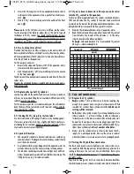
long hose to the exit. Slide hoses as far as they will go onto the
hose connectors and fix with coupling rings.
IMPORTANT: The arrow on the check valve must point in the CO
2
flow direction, i.e. from the CO
2
source to the diffusor (Flipper)!
���
•
Connect the short hose to the pressure reducer and secure with
the coupling ring.
���
2.3 Connect CO
2
flipper
•
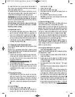
Rinse Flipper with warm tap water (no detergents!).
���
•
Moisten the hose connector slightly and fit the CO
2
supply hose.
���
•
Choose a spot in the aquarium which is as dark as possible (to
prevent algae growth) and where the water movement is good.
•
Fix Flipper in vertical position, at least 5 cm below the surface of
the water.
���
2.4 Connect to the power supply
The integrated solenoid valve enables the supply of CO
2
to be con-
trolled:
1 With a time switch
This serves to cut off the CO
2
supply at night, as plants do not con-
sume any CO
2
during the night.
Tip:
Connect the pressure reducer
to the time switch which is also used to control your aquarium
lighting.
쐅
2 Or with a pH controller
A pH controller such as the
Dennerle pH controller Evolution
measures the pH value in the aquarium continuously and controls
the supply of CO
2
precisely and fully automatically via the Space
pressure reducer.
쐈
Control states:
Power ON = LED ON = solenoid valve open.
Power OFF = LED OFF = solenoid valve closed.
Your CO
2
fertilizer system is now ready for use.
3 Setting the amount of CO
2
(number of bubbles)
3.1 The right amount of CO
2
For lush plant growth, Dennerle recommends a CO
2
level in the aqua-
rium of approx.
20 to 25 mg/l.
Levels of CO
2
above 30 mg/l are not necessary for healthy plant
growth and should be avoided, so as to ensure that fish and other
creatures living in the aquarium are not subjected to any unnecessary
stress.
The CO
2
content can be determined by means of the CO
2
long-term test
(see 4) or by measuring carbonate hardness and pH value (see 4.7).
3.2 Setting the number of bubbles
The required number of bubbles is dependent on various factors, such
as the stock of plants, water movement and lighting intensity. The ap-
propriate CO
2
supply level thus requires to be determined individually
for the specific aquarium concerned.
Rule of thumb for the basic setting:
Begin at approx. 10 bub-
bles per minute per 100 l of aquarium water, i.e. 2 x 10 = 20 bub-
bles per minute for a 200 l aquarium.
Adjust the CO
2
supply to the desired CO
2
content in small steps spread
over several days. Please note: The more vigorously the surface of
the water is set in motion, the more CO
2
will be expelled from the
aquarium again.
•
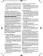
Slowly open the cylinder valve.
쐉
•
Slowly turn the setting knob on the pressure reducer towards “
+ ”(approx. 1 complete turn) until the first bubbles issue from
the Flipper.
씈
•
The desired number of bubbles can be set by turning the setting
knob to “ + ” or “ - ”.
Please note:
After adjusting the pressure reducer, there is al-
ways a delay before the number of bubbles is altered accordin-
gly (the hose acts as a pressure buffer). The number of bubbles
should thus be set in small steps, always waiting a couple of mi-
nutes until the new setting has stabilised.
Note:
If the setting knob is turned towards " – " in larger steps
of around 1 complete turn, the pressure reducer will release the
superfluous pressure through a small vent hole – audible as a
brief hiss. This venting serves to quickly stabilise the newly set
number of bubbles.
•
Check the number of bubbles regularly in the first few days, cor-
recting as necessary. After this initial period it is generally suffi-
cient to check the number of bubbles once a week.
4 Controlling CO
2
content with
the CO
2
long-term test
4.1 Mode of functioning
The colouring of the special CO
2
indicator varies according to the CO
2
content:
•
Blue = not enough CO
2
•
Green = CO
2
level ideal (approx. 20 mg/l)
•
Yellow = too much CO
2
The CO
2
content in the aquarium can be read directly from the colour
matching scale in mg/l.
4.2 Installation procedure for the CO
2
long-term
test Correct
•
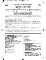
Remove test container from clasp. Pull off top part of test con-
tainer
씉
•
Shake the indicator down in the ampoule so that there is no in-
dicator in the neck of the ampoule. Twist off sealing tab.
씊
•
Fill the top part of the test container with the entire contents of the
ampoule.
씋
•
Slot bottom part of housing including conical reflector into the
top part. Check that the O-rings are fitted correctly.
씌
•
Turn test container carefully and insert in clasp.
씍
1-08415_0115_GA Mehrweg_Space_Layout 1 07.01.2015 11:27 Seite 12


