2.
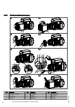
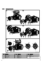
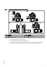
Remove fan cover (2) from the motor.
3.
Remove retaining ring (3) from the shaft.
4.
Remove fan wheel (4) from the shaft.
5.
Check the remaining thickness of brake disc (6), see
If the edge of armature plate (5) has reached mark (x) on collared pin (7), brake disc (6) must be replaced,
"Replacing the brake disc", Page 44.
6.
Check the brake air gap.
Brake air gap s
1min
= 0,35 mm - s
1max
= 1,2 mm
Tighten magnet assembly (3) with the three hexagon nuts (8) uniformly until the air gap is zero. Subsequent‐
ly loosen the three hexagon nuts (8) by angle α
1
, see
Measure air gap s
1
using feeler gauge (10) at three points around the circumference. If the measured value
is within the specified range, the motor can be re-assembled. If this is not the case, adjust again as required.
7.
Press fan wheel (4) onto the shaft and secure it with retaining ring (3).
Check to ensure that the retaining ring is correctly fitted. Ensure the retaining ring clicks correctly into place.
8.
Re-attach fan cover (2) to the motor with a tightening torque of 6,2 Nm.
214
39
5 44/120
914
43
Summary of Contents for DRF 200
Page 51: ...214 395 44 120914 51...


