4.4
Runway
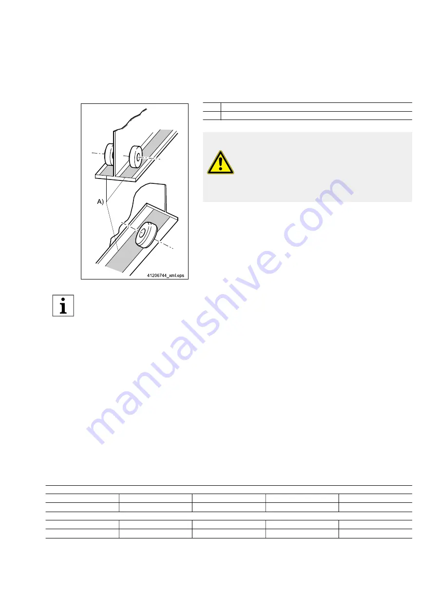
Fig. 6
Item Designation
A)
Hatched areas with primer coat only
Tab. 12
WARNING
Overload
Danger to life and limb if the trolley is subjected to an
overload.
The load capacity of the hoist unit must not exceed the
load capacity of the trolley.
When selecting a track, we recommend you specify the special profile
sections (see
"Trolley for KBK crane construction kit", Page 20) of
our Demag KBK crane construction kit. They are characterised by their
low deadweight. The cold-rolled track sections feature a smooth run‐
ning surface and offer the advantage of simple power supply by means
of trailing cables or integrated conductor lines.
I-beam girders and box-section girders that have parallel flanges can al‐
so be used tracks.
In the interest of good travel characteristics, we recommend the use of much larger curve radii, see
Page 19.
● Wear of the travel wheels is highly dependent on the curve radius. The force required to move the load may
be much higher on small curve radii in connection with heavy loads.
● The travel wheels and guide rollers may display increased wear in installations featuring intensive operation.
Displacement between the rails and gaps at the joint must be avoided. Any displacement between the rails should
be ground flat, if required.
I-beam tracks should be bent with the utmost care to obtain an even and regular curve. Ready-made curved sec‐
tions are available for our special track.
Travel on I-beam tracks must in no way be obstructed by protruding suspension pins, bolt heads, clamping plates
and butt straps, etc. These types of obstruction can be avoided by using our special track section.
In unclean environments, the running surface of the track should be cleaned regularly and should be free of oil
and grease.
Resilient buffers should be mounted at the level of the travel wheel axle at the ends of tracks to prevent the trolley
from derailing (see
The running surfaces of rails and for friction wheel travel drives on crane girders and runways must only be given
a primer coat of 40 µ in the area of the wheels, see (A)
Fig. 6, Page 19. Travel characteristics would be im‐
paired by a top coat.
Curve radii
Minimum medium horizontal curve radius
Flange width b
[mm]
≥ 100
< 200
< 300
Curve radius R
hor min
[mm]
> 800
> 850
> 900
Minimum medium vertical curve radius (gradient radius)
Flange thickness t
[mm]
10 - 19
20 - 25
28 - 30
Curve radius R
vert min
[mm]
> 2000
> 2500
> 3000
Tab. 13
214
39
5 44/120
914
19
Summary of Contents for DRF 200
Page 51: ...214 395 44 120914 51...


