Chapter 3 Profile and Parts
3-3
3_
3.3
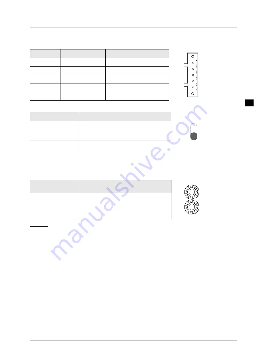
CANopen Port
PIN
Signal
Description
4
GND
SHLD
CAN-
CAN+
5
3
2
1
1
GND
0 VDC
2
CAN_L
Signal-
3
SHLD
Shielded
4
CAN_H
5
-
Reserved
3.4
RUN/STOP Switch
RUN/STOP Switch
Description
RUN
STOP
STOP → RUN
1. To re-detect the extension module.
2. To read/write the data in the extension
module.
RUN → STOP
To stop reading/writing the data in the extension
module.
3.5
Address Switches
The switches are used for setting up the node address of RTU-CN01 on CANopen network. Range: 1~7F (0,
80~FF are forbidden).
Switch setting
Description
N
O
D
E
AD
D
R
ES
S
x16
0
x16
1
1~7F
Valid CANopen node address
0, 80~FF
Invalid CANopen node address
Example:
If you need to set the node address of RTU-CN01 to 26 (1AH), simply switch the corresponding switch of
x16
1
to 1 and the corresponding switch of x16
0
to A.
Note:
Please set up the node address when the power is switched off. After the setup is completed, re-power
RTU-CN01.
When RTU-CN01 is operating, changing the setting of the node address will be invalid.
Use the slotted screwdriver to rotate the switch carefully in case the switch is scratched.
Summary of Contents for RTU-CN01
Page 11: ...RTU CN01 Operation Manual 2 6 _2 MEMO...
Page 43: ...RTU CN01 Operation Manual 5 22 5 MEMO...
Page 53: ...RTU CN01 Operation Manual 6 10 _6 MEMO...
Page 68: ...Chapter 7 Application Examples 7 15 7_ Note Baud rate conversion 1 Mbps 1000 Kbps 1000000bps...
Page 75: ...RTU CN01 Operation Manual 7 22 _7 The complete configuration of Send PDO mappings is as below...


