


ISOLATED ANALOG
SM15K INTERFACES
18 / 19
DELTA ELEKTRONIKA B.V.
rev. Nov. 2019
7.5
UNIT CONFIGURATION
The unit will automatically detect the new inserted interface.
The interface icon will be shown in the display, see fig 7 - 3.
For programming the voltage and/or current via the interface,
set the correct source for CV and CC respectively, see below
example.
o
For example the interface is mounted in slot2.
To program the CV-settings via this interface, via the front
menu go to CONFIGURATION -> SOURCE -> Vsettings
and set it to Slot2.
To program also the CC-settings via this interface, go to
CONFIGURATION -> SOURCE -> Isettings and also set it
to Slot2.
Instead of doing this via the Front Menu, the source can
also be set via the web interface or via Ethernet commands
if the unit is connected to the network via LAN.
7.6
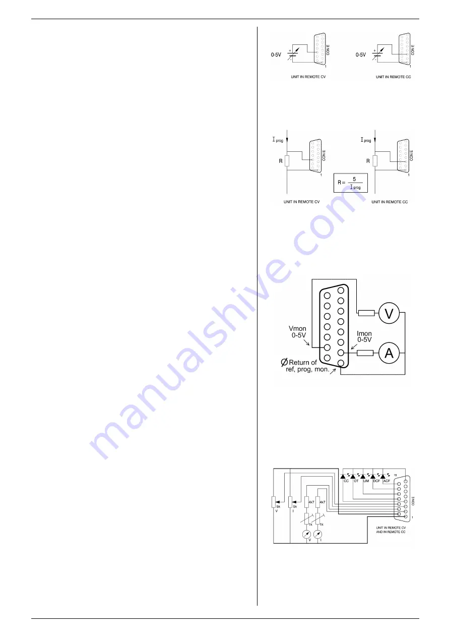
ANALOG PROGRAMMING
The output voltage and current can be programmed by a
voltage in the range of 0 - 5V (default setting) or 0 - 10V,
proportionally to the full output voltage and current. (see
fig. 7 - 4).
o
Note that a voltage at the I-prog input (pin3), sets both the
value for CC+ and CC-. Thus ap5V on pin3 on an
SM500-CP-90, sets CC+ to +90A, and CC- to
–90A.
o
CC+ and CC- cannot be programmed to a different value via
the analog input.
o
A negative input voltage is ignored and sets CC+ and CC-
to 0A.
The range 0 - 5V or 0 - 10V can be selected by ethernet
command only. See
further details.
Both have a protection circuit formed by a series resistor and
a parallel zener diode. The capacitor limits the speed to a
safe value. Note that the programming inputs are floating with
regards the power output.
Turn the output on again with the OUTPUT ON/OFF button.
To program the unit by current instead of voltage, simply use
a parallel resistor as a current to voltage converter. (see
fig. 7 - 5).
The front display will show the programmed values for CV
and CC.
7.7
ANALOG MONITORING
The monitor outputs give a voltage in the range of 0 - 5V or
0 - 10V, proportional to the output current or voltage. The
output current can easily be measured using the I-monitor
(see fig. 7 - 6).
The range 0 - 5V or 0 - 10V can be selected by ethernet
command only. See ethernet programming manual for further
details.
Note that the monitor outputs are floating with regards the
power output (similar to signals from the ISO AMP).
The monitor outputs are buffered with op-amps and protected
with series resistors and parallel zener diodes.
The table in the interface datasheet shows the impedance
levels of the monitoring outputs.
The monitoring outputs can drive a meter directly (fig. 7 - 6).
Note:
on a pulsating load, the current monitor will not exactly
match the output current. This is mainly caused by the current
through the output capacitors.
7.8
STATUS SIGNALS
The status outputs have a separate Ø-connection (pin 8) to
avoid unwanted offsets in the programming.
All the status outputs are logic outputs. Logic "0" means the
output is 0 V, logic "1" means the output is 5 V. This makes it
possible to drive directly: an opto-coupler, a TTL gate or a
CMOS gate.
fig 7 - 4
Programming by voltage:
left voltage -, right current by programming.
fig 7 - 5
Programming by current
left voltage-, right current programming.
fig 7 - 6
Measuring the output voltage and current using
the monitoring signals.
fig 7 - 7
Remote control.


