Delta Elektronika SM15K Series Product Manual Download Page 11

ISOLATED CONTACTS 


SM15K INTERFACES 

11 / 19 

DELTA ELEKTRONIKA B.V. 

rev. Nov. 2019 


This interface provides 4 changeover relay contacts, an 
Enable input and an Interlock (additional to the standard 
SM15K Interlock). 


The Relay contacts can be controlled & monitored by 
Ethernet commands and the web interface. They can also be 
linked to several system statuses, like ACF, DCF, etc. 


The Interlock and Enable input can be monitored by Ethernet 
commands.  


Refer to the Ethernet programming manual for commands, 
chapter "Command Description", paragraph "Interfaces". 


The manual is stored inside every SM15K unit and can be 
downloaded via the web interface or from 

www.DeltaPowerSupplies.com

. 

4.6.1


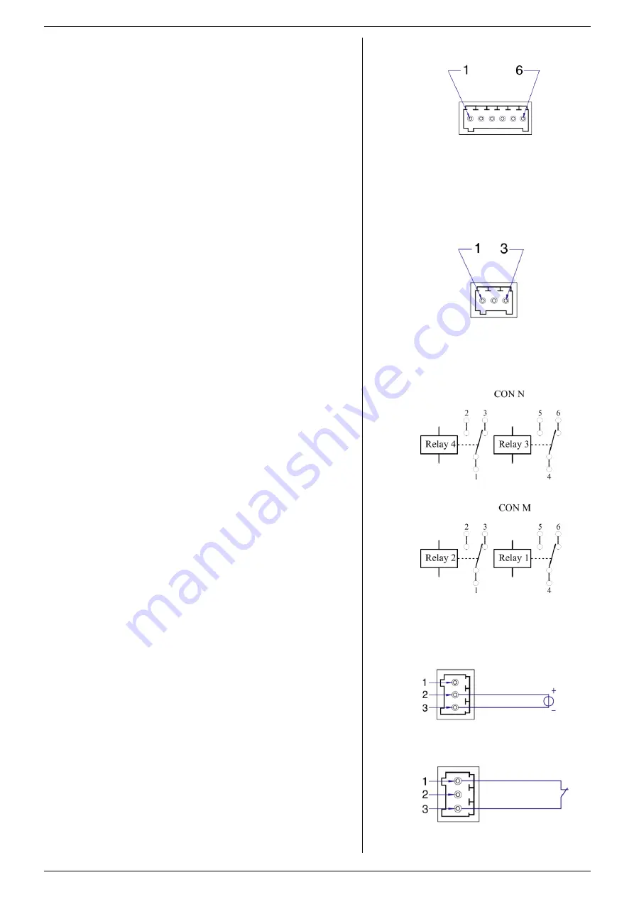
RELAY CONTACTS (CON M & CON N) 


Relay contacts (see fig. 4 - 4 & fig. 4 - 6) are as described 
below, during power off and when not set. The relay contacts 
can handle a maximum contact voltage of 60VDC. The 
maximum continuous current is 2A. 


Pinning CON M : 

o


6 = Relay 1 NC 

o


5 = Relay 1 NO 

o


4 = Relay 1 Common 

o


3 = Relay 2 NC 

o


2 = Relay 2 NO 

o


1 = Relay 2 Common 


Pinning CON N : 

o


6 = Relay 3 NC 

o


5 = Relay 3 NO  

o


4 = Relay 3 Common 

o


3 = Relay 4 NC  

o


2 = Relay 4 NO 

o


1 = Relay 4 Common 
 

4.6.2


INTERLOCK & ENABLE (CON K) 


The Interlock input (pin 1) is initially connected to pin 3 
(common) (see fig. 4 - 5). Replace the link by two wires and a 
switch (for example a cabinet door switch) when its function is 
required. 


The Enable input (24V, pin 2) impedance is approximately 
12kOhm and has a working range of 15V - 30V (see fig. 4 -7).  


Connect the common of the external voltage to pin 3. 


The Interlock and the Enable can not be used simultaneously 
(see fig. 4 - 8). 


All interlocks should be valid. 


Pinning CON K: 

o


3 = Common 

o


2 = Enable 

o


1 = Interlock 
 

4.7


TROUBLE SHOOTING 

4.7.1


INTERLOCK SYMBOL DISPLAYED 


Check the unit's standard interlock connection 


Check Interlock / enable connection on CON K. 

4.8


CALIBRATION 


Calibration of the interface is not applicable.. 


fig 4 - 4 

Pinning of CON M and N. 


fig 4 - 5 

Pinning of CON K. 


fig 4 - 6 

Pinning of CON M and N. 


fig 4 - 7 

15 - 30 V Enable. 


fig 4 - 8 

Interlock contact (door switch). 

Summary of Contents for SM15K Series

Page 1: ...on P0120 Contents 1 Safety Instructions 2 Sicherheitshinweise 3 Master Slave Interface 4 Isolated Contacts 5 Serial Interface 6 Digital User I O 7 Isolated Analog Interface Firmware Update It is stron...

Page 2: ...nd either the minus or plus DC power terminal is grounded the voltage on the DC power terminals and sense connections can be considered safe Caution 1 If a low voltage unit has both DC power terminals...

Page 3: ...covers Safety cover s are used to cover potentially hazardous voltages Observe the following when removing safety cover s Switch off the unit Disconnect the unit from the mains supply or power outlet...

Page 4: ...als sicher angesehen werden wenn die minus DC Anschlussklemme des Ger ts im Verh ltnis zur Erdung 1000 VDC 707 Vpk nicht berschreitet f r SM70 CP 450 SM210 CP 150 und SM500 CP 90 oder 1500VDC 1060Vpk...

Page 5: ...ie Folgendes wenn Sie die Sicherheitsabdeckung en entfernen Ger t ausschalten Ger t von dem Versorgungsnetz oder der Stromquelle trennen Warten Sie 5 Minuten damit interne Kondensatoren sich entladen...

Page 6: ...er In the front menu go to SYSTEM INFO UNIT VERSION If an update is required refer to the SM15K unit manual how to do this 3 4 HARDWARE INSTALLATION Warning Never make connections to the Power Inputs...

Page 7: ...first insert the bolts with crinkle washers in all DC power terminals Then assemble the entire strip to the DC power terminals This because bolts cannot be inserted in the DC power terminals once the...

Page 8: ...rip because it will burn out o Place the special M S parallel safety covers over the output terminals o Cover with marking DWG2532 is for the outputs of the upper and lower units Cover DWG2533 is for...

Page 9: ...own in the display see fig 3 6 The master or slave can also be configured via the web interface or using Ethernet commands After changing master or slave settings stored sequences need to be rebuilt d...

Page 10: ...how to do this 4 4 HARDWARE INSTALLATION Warning Never make connections to the Power Inputs and Outputs or the Sense Connector when the SM15K unit is connected to the mains supply or power outlet Safe...

Page 11: ...N M o 6 Relay 1 NC o 5 Relay 1 NO o 4 Relay 1 Common o 3 Relay 2 NC o 2 Relay 2 NO o 1 Relay 2 Common Pinning CON N o 6 Relay 3 NC o 5 Relay 3 NO o 4 Relay 3 Common o 3 Relay 4 NC o 2 Relay 4 NO o 1 R...

Page 12: ...to the SM15K unit manual how to do this 5 4 HARDWARE INSTALLATION Warning Never make connections to the Power Inputs and Outputs or the Sense Connector when the SM15K unit is connected to the mains su...

Page 13: ...e monitored Download the manual Ethernet Sequencer Programming SM15K for details 5 9 TROUBLE SHOOTING Check the programming source is set to the correct slot Check the output is switched ON the Interl...

Page 14: ...the unit must be in CC mode and when programming a power the unit must be in CP mode 5 10 CALIBRATION Calibration of the interface is not applicable 5 11 Settings Settings via the web page o Bus type...

Page 15: ...red refer to the SM15K unit manual how to do this 6 4 HARDWARE INSTALLATION Warning Never make connections to the Power Inputs and Outputs or the Sense Connector when the SM15K unit is connected to th...

Page 16: ...pin 15 The user inputs have a working range of 2V 30V use a common zero and have an impedance of approximately 22kOhms The maximum load of the 5V is 100mA See figure 6 4 and table 6 1 for the pinning...

Page 17: ...mware package is P0120 or higher In the front menu go to SYSTEM INFO UNIT VERSION If an update is required refer to the SM15K unit manual how to do this 7 4 HARDWARE INSTALLATION Warning Never make co...

Page 18: ...afe value Note that the programming inputs are floating with regards the power output Turn the output on again with the OUTPUT ON OFF button To program the unit by current instead of voltage simply us...

Page 19: ...ble to use a relay contact or a switch to shut the unit down see fig 7 9 In standby mode the power supply consumes very little power Note also via Eth or other interfaces RSD can be activated 7 10 REF...

Reviews: