Installing System Components
139
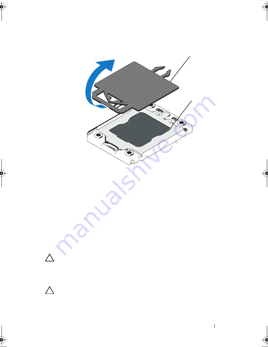
Figure 3-25.
Removing the Cover From the Processor Socket
2
Remove the processor from the packing material by the processor’s edges
only. Do not touch the bottom of the processor. Handle the processor
carefully with your fingers on the side edges. Place your hand beneath the
processor when you are moving it to the system.
3
Locate the pin 1 indicator on the system board socket.
4
Locate the pin 1 indicator on the top of the processor. The pin 1 indicator
is shown as a triangle on the top of the processor. See Figure 3-24.
CAUTION:
Positioning the processor incorrectly can permanently damage the
system board or the processor. Be careful not to bend the pins in the socket.
5
Place the processor over the socket with each pin 1 aligned and level. See
Figure 3-24.
CAUTION:
Do not use force to seat the processor. When the processor is
positioned correctly, it engages easily into the socket.
1
plastic socket cover
2
processor socket
1
2
book.book Page 139 Thursday, February 18, 2010 2:06 PM
Summary of Contents for PowerEdge R810
Page 1: ...Dell PowerEdge R810 Hardware Owner s Manual Regulatory Model E05S Regulatory Type E05S001 ...
Page 80: ...80 Using the System Setup Program and UEFI Boot Manager ...
Page 160: ...160 Installing System Components ...
Page 194: ...194 Jumpers and Connectors ...
Page 196: ...196 Getting Help ...
Page 202: ...Index 202 ...


