


Installing System Components
75
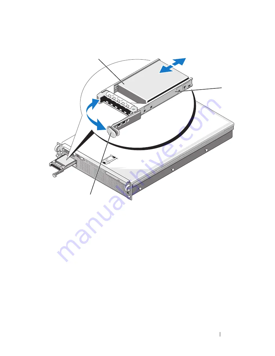
Figure 3-5.
Installing a Hot-Plug Hard Drive
3
Install the hot-plug hard drive.
a
Open the handle on the hard-drive carrier.
b
Insert the hard-drive carrier into the drive bay until the carrier
contacts the backplane.
c
Close the handle to lock the drive in place.
4
Replace the front bezel, if it was removed in
step 1.
1
hard drive
2
drive carrier
3
drive carrier release handle
3
1
2
Summary of Contents for PowerEdge R805 System
Page 46: ...46 About Your System ...
Page 176: ...176 Getting Help ...
Page 192: ...192 Glossary ...
Page 200: ...200 Index ...


