


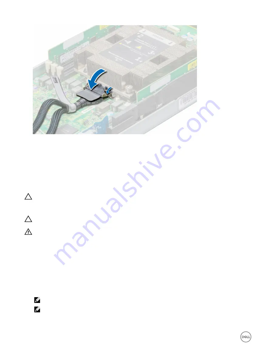
Figure 38. Securing the fabric connector
Next steps
1.
Install the air shroud.
2.
Follow the procedure listed in the After working inside your system section.
Removing the processor and heat sink module
Prerequisites
CAUTION: Many repairs may only be done by a certified service technician. You should only perform troubleshooting and
simple repairs as authorized in your product documentation, or as directed by the online or telephone service and support
team. Damage due to servicing that is not authorized by Dell is not covered by your warranty. Read and follow the safety
instructions that are shipped with your product.
CAUTION: Never remove the heat sink from a processor unless you intend to remove the processor. The heat sink is
necessary to maintain proper thermal conditions.
WARNING: The heat sink may be hot to touch for some time after the system has been powered down. Allow the heat
sink to cool before removing it.
1.
Follow the safety guidelines listed in the Safety instructions section.
2.
Follow the procedure listed in the Before working inside your system section.
3.
Remove the sled from the enclosure.
4.
Remove the air shroud.
5.
If installed, disconnect the fabric cable from the fabric processor.
6.
Keep the Torx T30 screwdriver ready.
Steps
1.
Using the Torx screwdriver, loosen the screw identified with number 4 on the heat sink label.
NOTE: To remove the processor and heat sink module, remove the screws in reverse order-4321.
NOTE: Ensure that the screw is loosened before moving on to the next screw.
86
Summary of Contents for PowerEdge C6320p
Page 1: ...Dell PowerEdge C6320p Owner s Manual Regulatory Model B08S Series Regulatory Type B08S004 ...
Page 10: ...Figure 2 Supported configuration for the C6320p sled with an Intel Phi 72xx processor 10 ...
Page 11: ...Figure 3 Supported configuration for the C6320p sled with an Intel Phi 72xx F processor 11 ...
Page 25: ...Figure 16 Enclosure Service Tag location on the left front panel 25 ...
Page 106: ...Figure 55 Removing an expansion card filler bracket 106 ...


