


Stacking Dell PowerConnect Switches: 8132, 8132F, 8164, 8164F
27
Web interface method
The example below shows how to add a stack member to an existing stack using the Web user
interface. Before cabling an additional member to a stack, perform the steps below to setup the
switch to join the stack. Once configured, continue to follow the instructions for cabling to complete
the task. This works best when adding one stack member at a time. If multiple new members are to
be added, follow these directions and complete the install of one before going to the next. Complete
these steps again for each remaining switch to be added.
Caution:
5.0.x.x firmware will not load on a switch with the newer “B1” CPU. It is therefore
recommended to upgrade all PowerConnect 8100 switches to the latest firmware. See
“Important Firmware Update for PowerConnect 81xx Stacking” at the beginning of this
document for more information.
Note
: The example given below allows the new member to be added without preconfiguring
the existing stack, though the new member itself needs to be configured. To preconfigure a
stack before connecting the new stack member, consult the
User Guide
under
Preconfiguring a
Stack Member
.
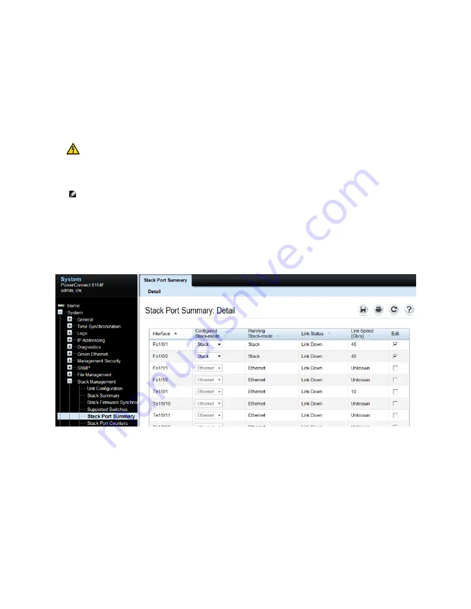
On the new member switch to be added to the stack, select System > Stack Management > Stack Port
Summary from the main navigation menu. In this example, two 40G QSFP+ interfaces F01/0/1 and
F01/0/2 will be used for stacking, though any of the interfaces shown may be used.
In the
Edit
column, select the check box to allow editing on the ports to be used for stacking. Then
use the drop-down menu in the
Configured Stack-mode
column to put each port in stack mode. The
Configured Stack Mode is now
Stack
, but the Running Stack-mode does not show Stack until the switch
is reloaded, as instructed below.
Save the configuration to the Startup-Configuration using the System > File Management > Copy Files
page.


